
Air baffles in railroad tunnels for decreased airflow therein and improved ventilation and cooling of locomotives

Active Publication Date: 2013-07-11
UNION PACIFIC RAILROAD
View PDF6 Cites 9 Cited by
  • Summary
  • Abstract
  • Description
  • Claims
  • Application Information

AI Technical Summary

Benefits of technology

The disclosure provides a system for improving ventilation in a tunnel by using air baffles that reduce airflow in the longitudinal direction of the tunnel. This increases the relative difference between the vehicle's speed and air speed in the tunnel annulus, when the vehicle passes through. This system can decrease airflow and provide better air quality for drivers and passengers in tunnels, improving safety and comfort.

Problems solved by technology

As freight trains pass through railroad tunnels, particularly at lower speeds, overheating and loss of power of one or more locomotives within the train, and / or stalling of the train, may occur.
This is a particular problem for long freight trains incorporating multiple locomotives, as the locomotives, especially those further back in the train, will be forced to intake that heated / contaminated air.
The combined result of these factors is that the locomotive(s) may experience overheating due to resulting excessive radiator water and engine lubricating oil temperatures, for example, with the locomotives thus de-rating in power output or sometimes losing traction power.
Also, lower air pressure in the tunnel, as caused by the piston effect, means less fresh air is available for intake and use in engine combustion.
This may result in the train stalling in the tunnel.
Such stalling incidents cause train delays, as well as risks to employees or personnel called to correct the problem.
However, such curtains have proved to be maintenance-intensive and have been used sparingly.

Method used


Image

  • Air baffles in railroad tunnels for decreased airflow therein and improved ventilation and cooling of locomotives
  • Air baffles in railroad tunnels for decreased airflow therein and improved ventilation and cooling of locomotives
  • Air baffles in railroad tunnels for decreased airflow therein and improved ventilation and cooling of locomotives

Examples


Embodiment Construction

)

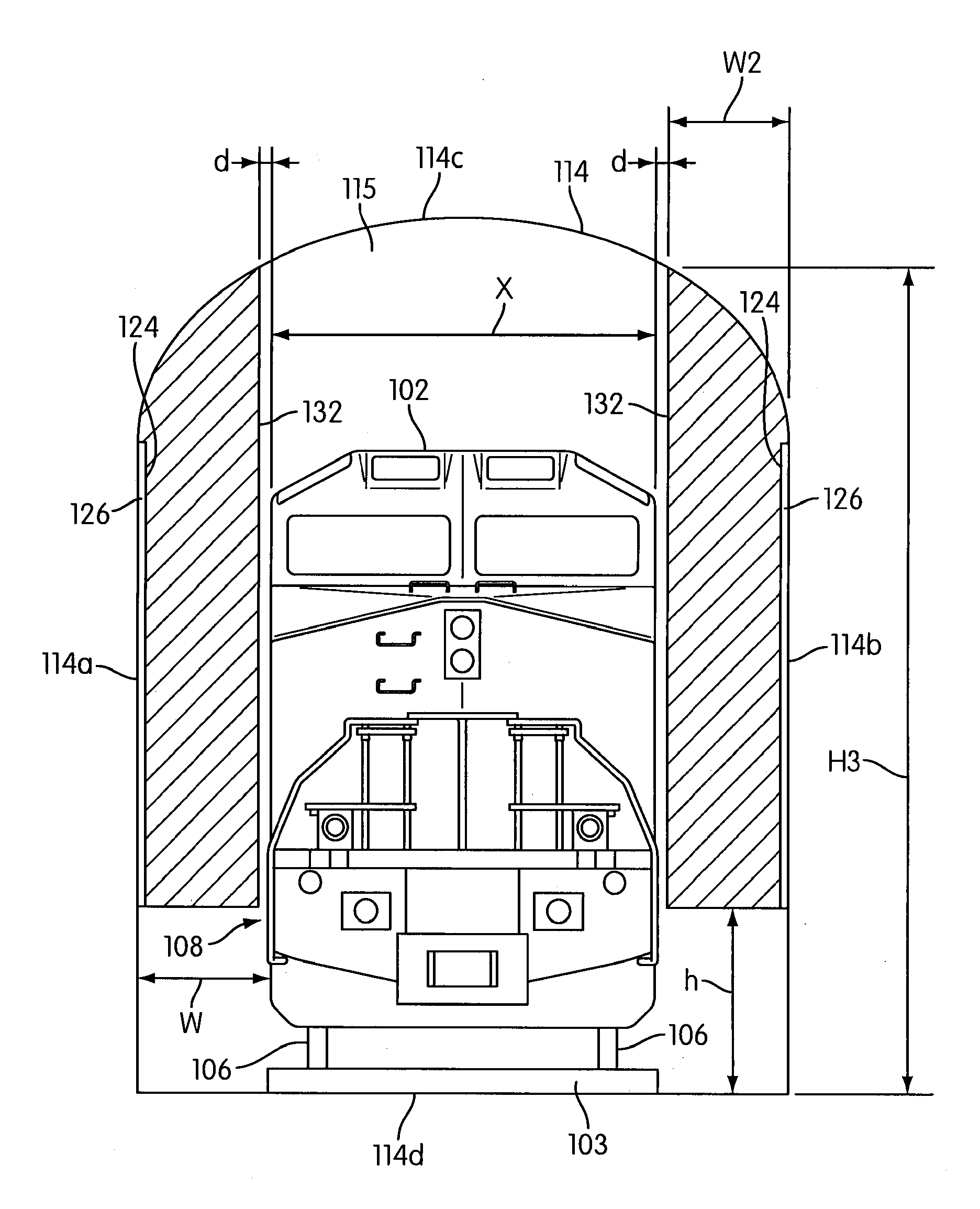
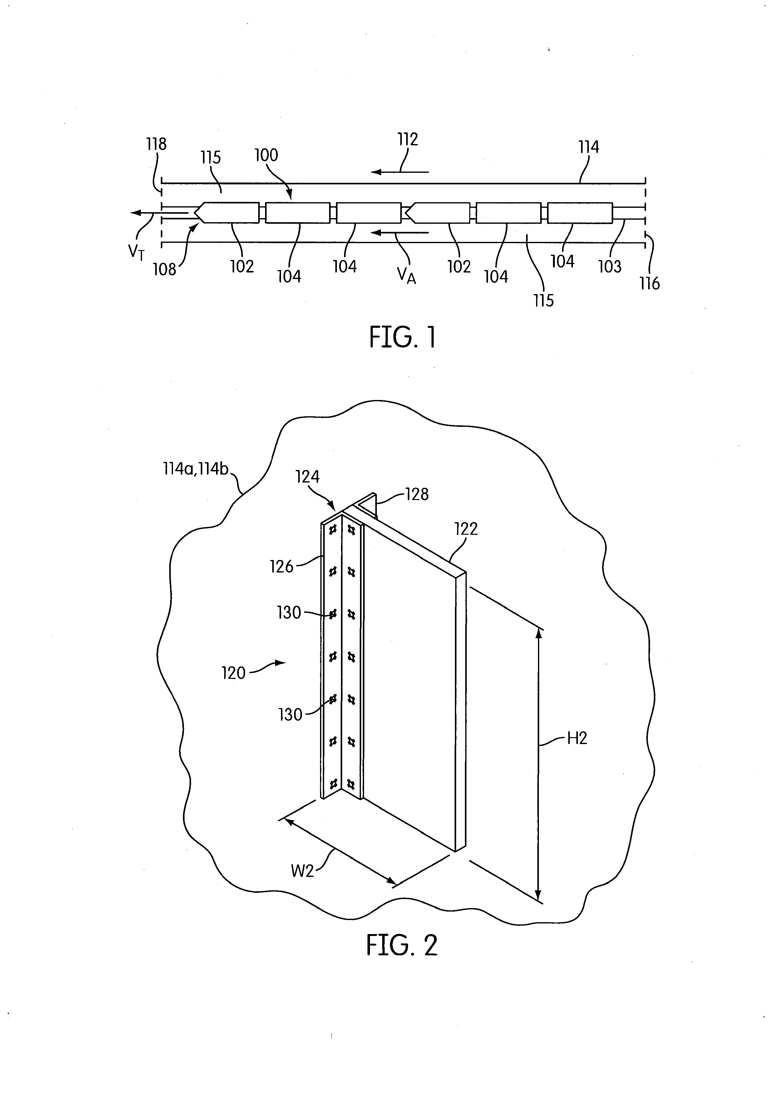
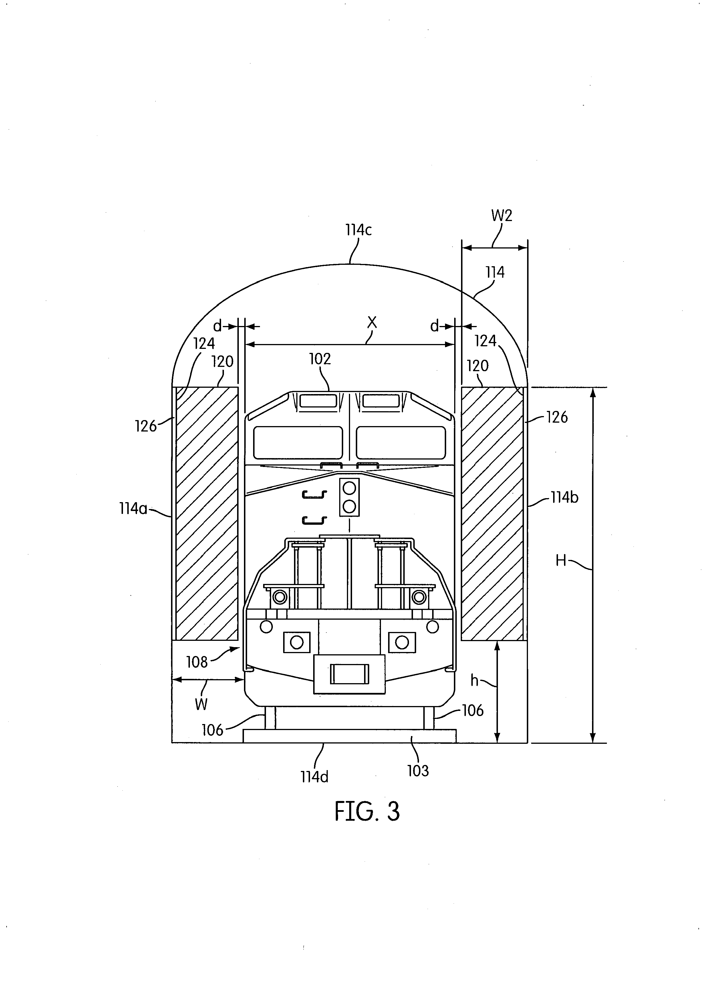
[0023]It is generally known that the combined discharge of both engine exhaust and heat-carrying “cooling” air into the roofspace of the tunnel results in downward flow of exhaust, thus contaminating air in the tunnel annulus, which is defined as the area between the sides of the train (e.g., locomotive and cars) and the walls of the tunnel. FIG. 1 illustrates an overhead view of a freight train 100 travelling through a tunnel 114 along a track or rails 103 (or path). The freight train 100 generally comprises at least one (leading) locomotive 102 at a front end 108 of the train for pulling one or more cars 104 (e.g., in a series or set) on railroad tracks or rails 103. A “car” may be generally referred to as a body with track engaging wheels 106 (e.g., see FIG. 3) and couplings that is connected in a train 100 for transporting items, and will become more evident by the description below.

[0024]In some cases, freight train 100 is used to transport goods, cargo, and other items that a...


PUM


Abstract

Disclosed is a system and method for decreasing airflow and improving ventilation within a tunnel, such as a railroad tunnel, including a path for movement of a vehicle (e.g., train) therethrough. The system has a plurality of air baffles mounted within the tunnel, each device comprising a body and a mounting device. Each mounting device positions each body inside and along the length of the tunnel between the entrance and the exit. The air baffles are configured to restrict airflow at least in part in a longitudinal direction of the tunnel, thereby increasing a relative difference between a vehicle speed and air speed in a tunnel annulus when the vehicle passes through the tunnel. The restriction (e.g., decrease) of airflow in the tunnel reduces the piston effect resulting from the vehicle or train passing through, thus reducing emissions and heat generated by the locomotives in the tunnel.

Description

BACKGROUND[0001]1. Field[0002]The present disclosure is generally related to improving ventilation within railroad tunnels by using air baffles to increase relative movement of air in the tunnel annulus as a train passes through.[0003]2. Description of Related Art[0004]Freight trains are often used to transport goods. As freight trains pass through railroad tunnels, particularly at lower speeds, overheating and loss of power of one or more locomotives within the train, and / or stalling of the train, may occur. This may often be caused by at least one of two factors: (1) the “piston effect,” and (2) accumulation of heated engine exhaust, hot radiator air, and pollutant gases. The “piston effect”—also referred to as the plunger effect—is a result of displacement flow which is the bulk movement of air or gases in a space, such as by the action of a piston or plunger in a cylinder-like shape. In the case of a train moving through a tunnel, for example, a leading locomotive (i.e., piston)...

Claims


Application Information

Patent Timeline
IPC IPC(8): E21F1/00
CPCE21F1/003Y02T30/00
Inventor IDEN, MICHAEL E.
Owner UNION PACIFIC RAILROAD
Learn More