
Method and apparatus for providing communication service to mobile station by multiple base stations in cooperation in wireless communication system

a wireless communication system and mobile station technology, applied in electrical apparatus, distributed allocation, transmission path sub-channel allocation, etc., can solve problems such as resource allocation conflicts, significant overhead and time delay, and ineffective distribution control schemes in improving system yield. the effect of system performan

Active Publication Date: 2013-07-11
SAMSUNG ELECTRONICS CO LTD
View PDF3 Cites 42 Cited by
  • Summary
  • Abstract
  • Description
  • Claims
  • Application Information

AI Technical Summary

Benefits of technology

The present invention is about efficient allocation of resources between a master and a slave base station in a wireless communication system. The master base station creates a resource allocation cooperative cell and shares information with other base stations about which part of the resource allocation was used, which helps to optimize the performance of the system. The base stations also exchange information about the resource allocation to resolve any conflicts that might arise during the allocation process. This allows for smoother operation and better service provision to mobile stations.

Problems solved by technology

However, in the centralized control scheme, in a case where a BS simultaneously belongs to multiple cooperative cells, if a resource allocation command received from a master BS of each cooperative cell instructs allocation of the same resources in a duplicate manner, resource allocation conflicts may occur.
In this case, if a master BS of each cooperative cell coordinates the resource allocations through signaling with other BSs in order to prevent the resource allocation conflicts, significant overhead and time delay may occur.
In addition, the distributed control scheme may not be efficient in improving the system yield through the original inter-cell cooperation of the cooperative cells.

Method used


Image

  • Method and apparatus for providing communication service to mobile station by multiple base stations in cooperation in wireless communication system
  • Method and apparatus for providing communication service to mobile station by multiple base stations in cooperation in wireless communication system
  • Method and apparatus for providing communication service to mobile station by multiple base stations in cooperation in wireless communication system

Examples


first embodiment

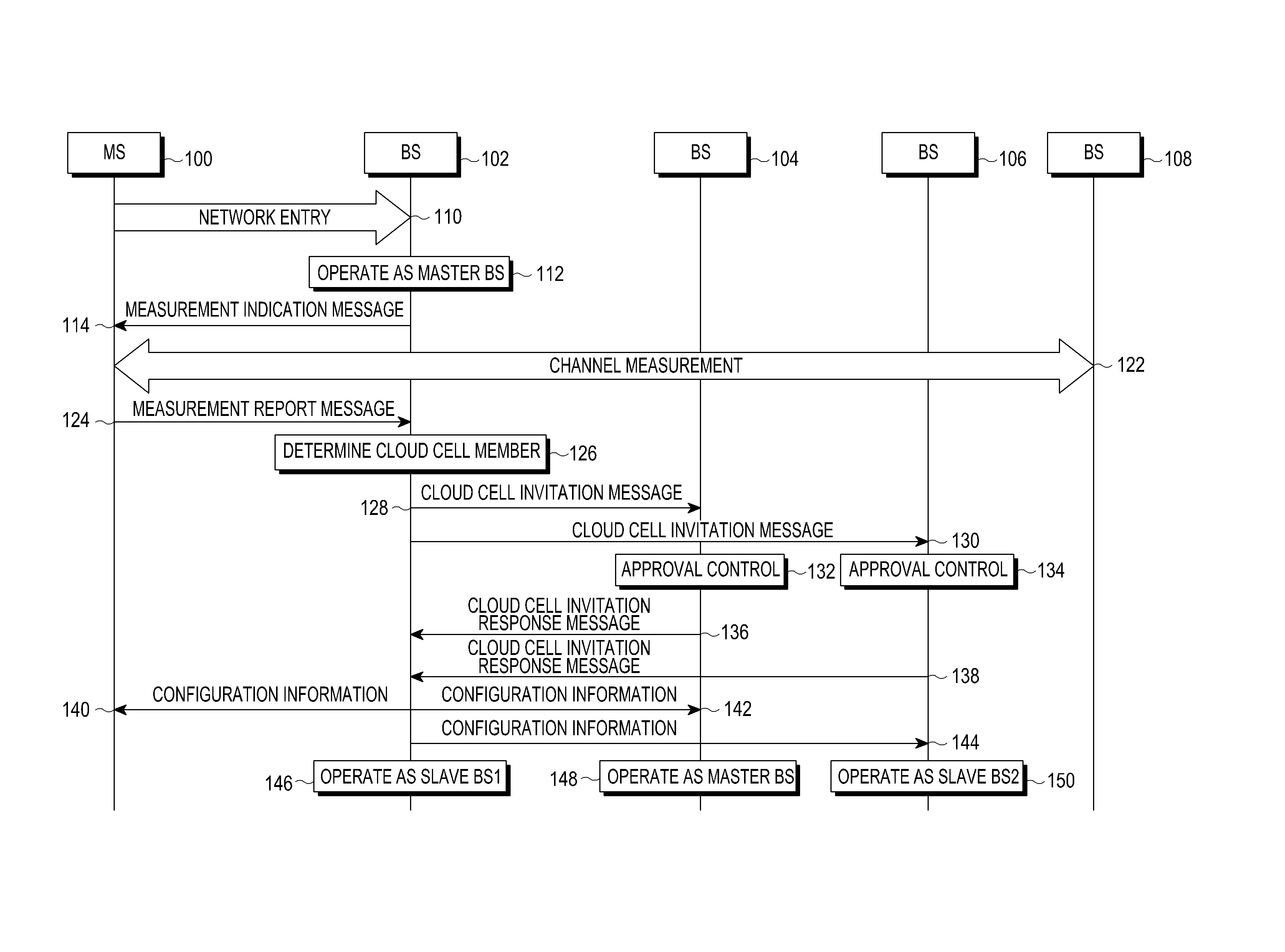
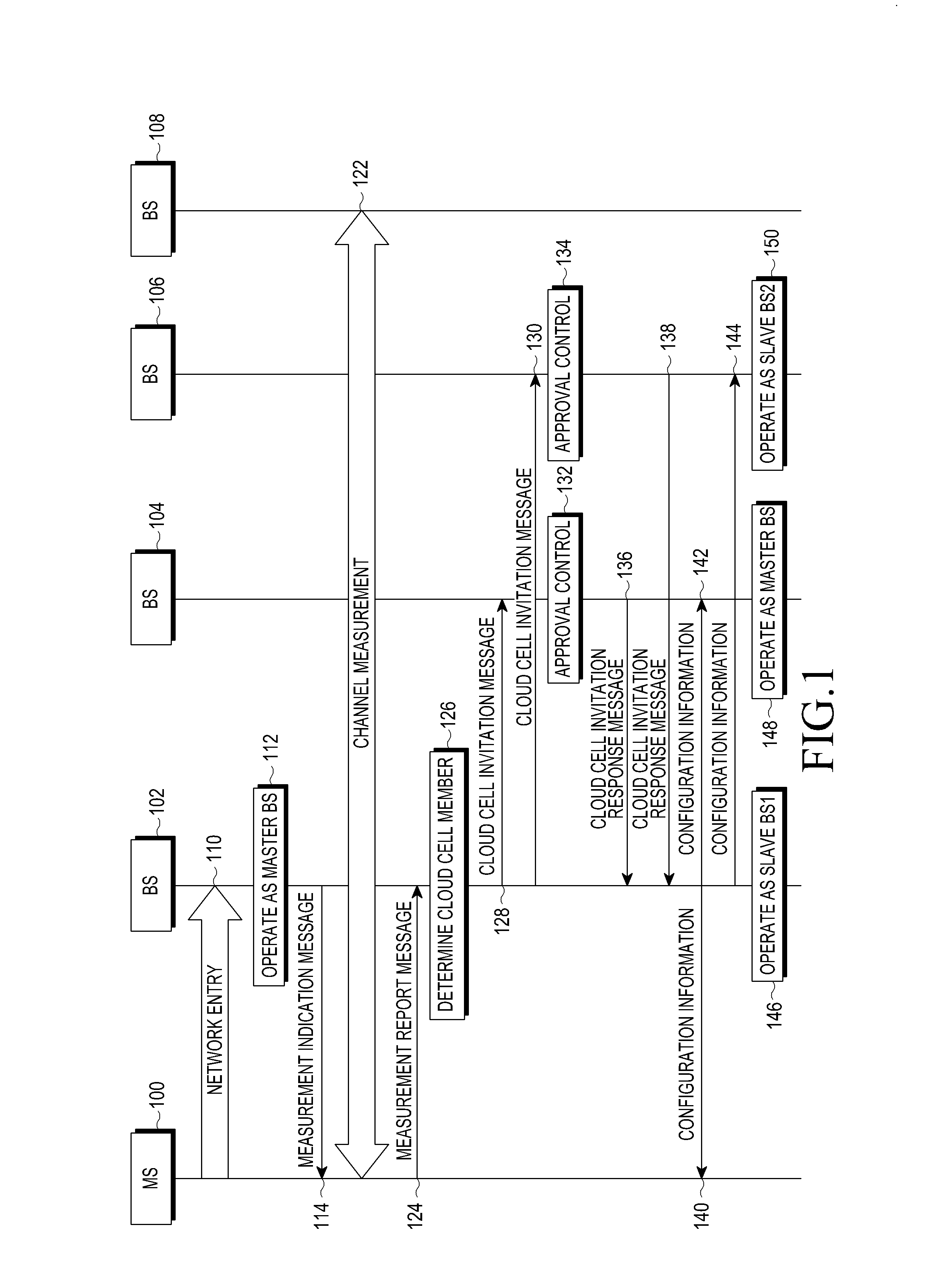
[0035]FIG. 1 illustrates a procedure for configuring a cloud cell in a communication system according to the present invention.

[0036]Referring to FIG. 1, the communication system includes an MS 100, a first BS 102, a second BS 104, a third BS 106 and a fourth BS 108.

[0037]The MS 100 performs a network entry operation to one of its neighbor BSs, for example, to the first BS 102 in step 110, and then the first BS 102 operates as a master BS in step 112. The first BS 102 operating as the master BS sends a measurement indication message to the MS 100 in step 114 to instruct the MS 100 to measure channels of its neighbor BSs, and the MS 100 measures channels of the first to fourth BSs 102 to 108 in step 122, and transmits the measurement results to the current master BS or the first BS 102 using a measurement report message in step 124. The measurement report message may be sent periodically, or may be sent intermittently by a command from a master BS.

[0038]Upon receiving the measurement...

second embodiment

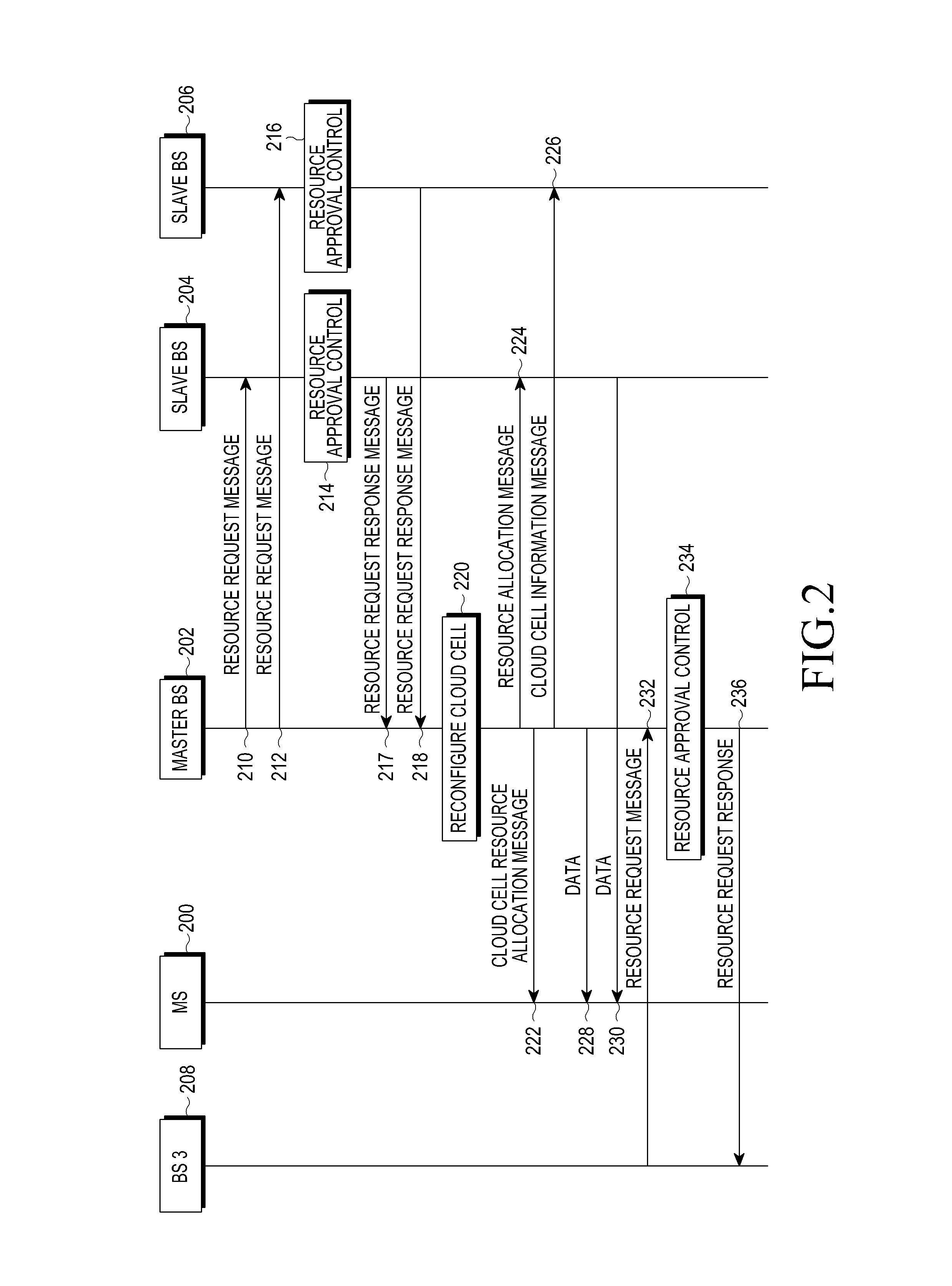
[0044]FIG. 2 illustrates a procedure for reconfiguring a cloud cell in a communication system according to the present invention.

[0045]Although a cloud cell consisting of a master BS 202, a first slave BS 204 and second slave BS 206 will be considered in FIG. 2 by way of example, the present invention is not limited thereto, and the cloud cell may consist of one master BS and one or more slave BSs.

[0046]In steps 210 and 212, the master BS 202 sends a resource request message for requesting resource allocation to the first and second slave BSs 204 and 206 at every scheduling cycle. The master BS 202 may send a resource request message to the first and second slave BSs 204 and 206 at any time, even though the time of sending the resource request message is not at a predetermined scheduling cycle. The resource request message includes information on a required amount of resources, and a type of traffic in service such as real-time traffic, non-real-time traffic, etc. In a case where th...

third embodiment

[0055]FIG. 3 illustrates a procedure for changing a master BS in a cloud cell-based communication system according to the present invention.

[0056]Referring to FIG. 3, the communication system includes an MS 300, a master BS 302, a first slave BS 304 and a second slave BS 306. The master BS 302, the first slave BS 304 and the second slave BS 306 constitute a first cloud cell, and the first and second slave BSs 302 and 304 are assumed to be members of a second cloud cell.

[0057]In step 310, the master BS 302 of the first cloud cell determines to change a master BS of the first cloud cell if it cannot provide the minimum service quality or minimum Quality of Service (QoS) to the MS 300 or if its channel state is less than a threshold for a predetermined time. The channel state information may be acquired from a measurement report message received, for example, from the MS 300 or from any other suitable source.

[0058]Upon determining to change the master BS, the master BS 302 the sends a ...


PUM


Abstract

A method and an apparatus for providing a service to a Mobile Station (MS) by a plurality of Base Stations (BSs) operating in cooperation in a wireless communication system are provided. The method includes configuring, by a master BS, a first cooperative cell including at least one slave BS, sending a resource request message for requesting resource allocation to the at least one slave BS included in the first cooperative cell, receiving, from each of the at least one slave BS, a resource request response message including resource approval control results for the resource allocation request, changing member BSs constituting the first cooperative cell based on the resource request response message, and allocating resources to an MS that is served in the first cooperative cell.

Description

PRIORITY[0001]This application claims the benefit under 35 U.S.C. §119(a) of a Korean patent application filed on Jan. 9, 2012 in the Korean Intellectual Property Office and assigned Serial No. 10-2012-0002379, and a Korean patent application filed on May 11, 2012 in the Korean Intellectual Property Office and assigned Serial No. 10-2012-0050477, the entire disclosure of each of which is hereby incorporated by reference.BACKGROUND OF THE INVENTION[0002]1. Field of the Invention[0003]The present invention relates to a method and apparatus for providing a communication service to a Mobile Station (MS) by a plurality of Base Stations (BSs) in cooperation in a wireless communication system.[0004]2. Description of the Related Art[0005]A MS included in a wireless communication system may have a virtual cell that is formed flexibly or adaptively depending on the MSs moving path. The virtual cell may be considered to be a kind of cooperative cell that is formed for cooperative communication...

Claims


Application Information

Patent Timeline
Patent Type & Authority Applications(United States)
IPC IPC(8): H04W72/04
CPCH04W72/04H04W72/0426H04W24/10H04W72/27H04L5/0032
Inventor LEE, OK-SEONTAORI, RAKESHSEOL, JI-YUNCHANG, YOUNG-BINJEONG, CHEOL
Owner SAMSUNG ELECTRONICS CO LTD
Learn More