
Turning holder

Active Publication Date: 2013-07-18
ZHUHAI CHUNQIU OPTICAL INSTR
View PDF30 Cites 10 Cited by
  • Summary
  • Abstract
  • Description
  • Claims
  • Application Information

AI Technical Summary

Benefits of technology

The present invention is a device for rotating a holder body to aim at a target. It includes a base, a holder body with a rotary body, and a rotary shaft. The rotary body has a clamping sleeve, a pressure ring, and a locking means. The rotary shaft cover, rotary shaft, pressure spring, and steel ball create a compact and reliable locking mechanism. The structure allows for easy and flexible rotation of the holder body, making it convenient to use.

Problems solved by technology

Besides, the operation is troublesome and inconvenient, thereby causing big inconvenience to the users.

Method used


Image

  • Turning holder
  • Turning holder
  • Turning holder

Examples


Embodiment Construction

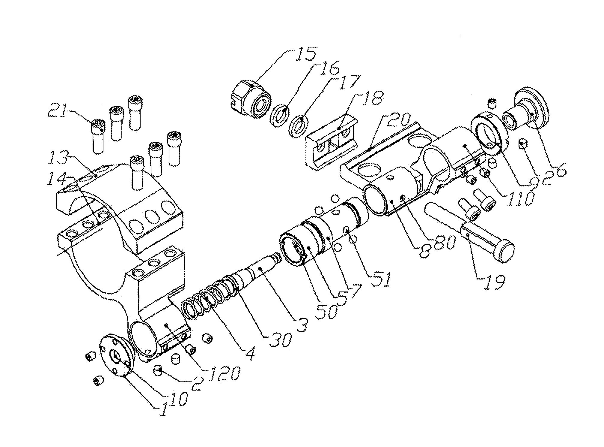
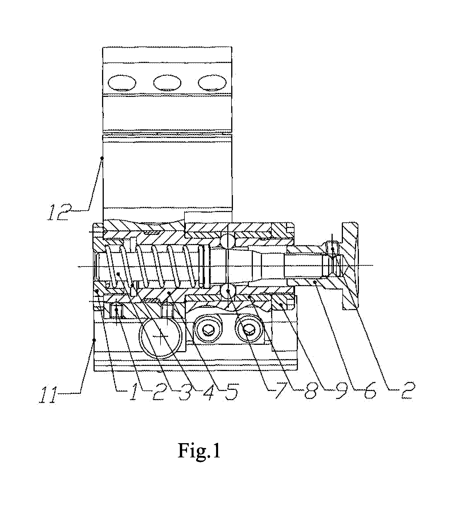
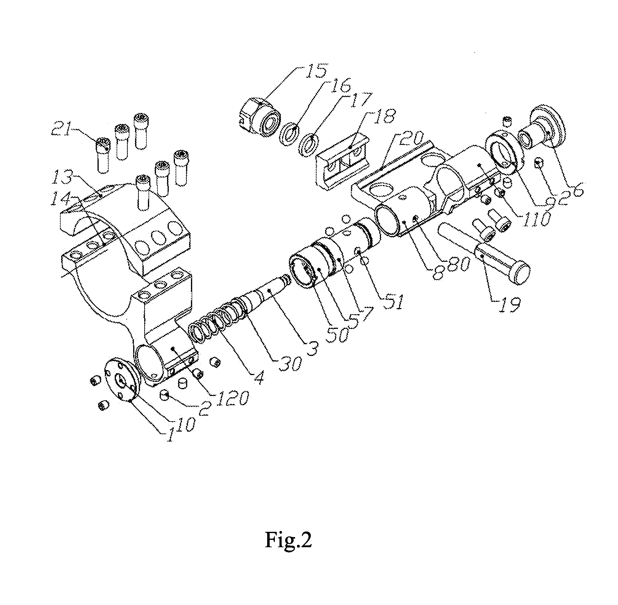
[0015]As shown in FIGS. 1, 2 and 3, the present invention comprises abase (11), a holder base (12) and a rotary body, wherein a base sleeve (110) is provided on the base, a holder sleeve (120) is provided on the holder body (12), and both the base sleeve (110) and the holder sleeve (120) are sleeved on the rotary body and are fixedly connected with the rotary body. The rotary body comprises a rotary shaft cover (1), a rotary shaft (3), a pressure spring (4), a shaft sleeve (5), a turning cap (6), steel ball(s) (7), a clamping sleeve for rotary shaft (8) and a pressure ring (9). The rotary shaft (3) is located in the cavity of the shaft sleeve (5), the rotary shaft cover (1) is positioned at one end of the shaft sleeve (5) and is fitted with the shaft sleeve (5), the rotary shaft cover (1) is fixed on the shaft sleeve (5) by a fixing screw (2), the pressure spring (4) is arranged on the rotary shaft (3) with one end pressing on the rotary shaft cover (1) and the other end pressing on...


PUM


Abstract

A turning holder enabling an easy operation and a convenient use without the need for repeated mounting and dismounting is provided. The turning holder comprises a base (11), a holder body (12), and a rotary body. A base sleeve (110) is provided on the base (11). A holder sleeve (120) is provided on the holder body (12). The rotary body includes a shaft sleeve (5), a clamping sleeve for rotary shaft (8), a pressure ring (9) and a locking means. The clamping sleeve for rotary shaft (8) is sleeved outside at a groove around an end of the shaft sleeve (5). The holder sleeve (120) is sleeved on the shaft sleeve (5) in a staggered position relative to the clamping sleeve for rotary shaft (8). The base sleeve (110) is sleeved around the clamping sleeve for rotary shaft (8) and fixedly connected therewith. The pressure ring (9) is sleeved around an end of the shaft sleeve (5) and presses the clamping sleeve for rotary shaft (8) from outside. The present invention can be widely used in the fields of firearms, bows and crossbows.

Description

FIELD OF THE INVENTION[0001]The present invention relates to a turning holder.BACKGROUND OF THE INVENTION[0002]At present, aimer has been widely used in the fields of firearms, bows and crossbows. Some auxiliary tools mounted on the firearm by holder are often required to be loaded when using the aimer. For example, in use of a red dot sight, a zoom lens is needed to amplify a target for a long distance and has to be dismounted for a short distance, thus the holder has to be mounted and demounted repeatedly. Besides, the operation is troublesome and inconvenient, thereby causing big inconvenience to the users.SUMMARY[0003]The technical problems to be solved by the present invention is to overcome the disadvantages of the prior art and provide a turning holder which is easy to operate and convenient to use without the need for repeated mounting and demounting.[0004]The technical scheme adopted by the present invention is: the present invention comprises a base, a holder body and a ro...

Claims


Application Information

Patent Timeline
IPC IPC(8): F41G1/387
CPCF41G11/003F41G1/387
Inventor HE, YINQUANLI, PANFENGLIN, DAYUN
Owner ZHUHAI CHUNQIU OPTICAL INSTR
Features
  • Generate Ideas
  • Intellectual Property
  • Life Sciences
  • Materials
  • Tech Scout
  • Unparalleled Data Quality
  • Higher Quality Content
  • 60% Fewer Hallucinations
Learn More