Shiplap joint

a technology of shiplap and joint, applied in the field of building panels, can solve the problems of requiring additional labor during application and eventual replacement, and gaps in coverage,

Inactive Publication Date: 2013-07-18
EI DU PONT DE NEMOURS & CO
View PDF6 Cites 12 Cited by
  • Summary
  • Abstract
  • Description
  • Claims
  • Application Information

AI Technical Summary

Problems solved by technology

Filler materials have the disadvantage of requiring additional labor during application and eventual replacement as the material weathers due to exposure to the elements.
However, gaps will develop in the coverage when the panels experience contraction, as illustrated in FIG.

Method used


Image

  • Shiplap joint
  • Shiplap joint
  • Shiplap joint

Examples


Embodiment Construction

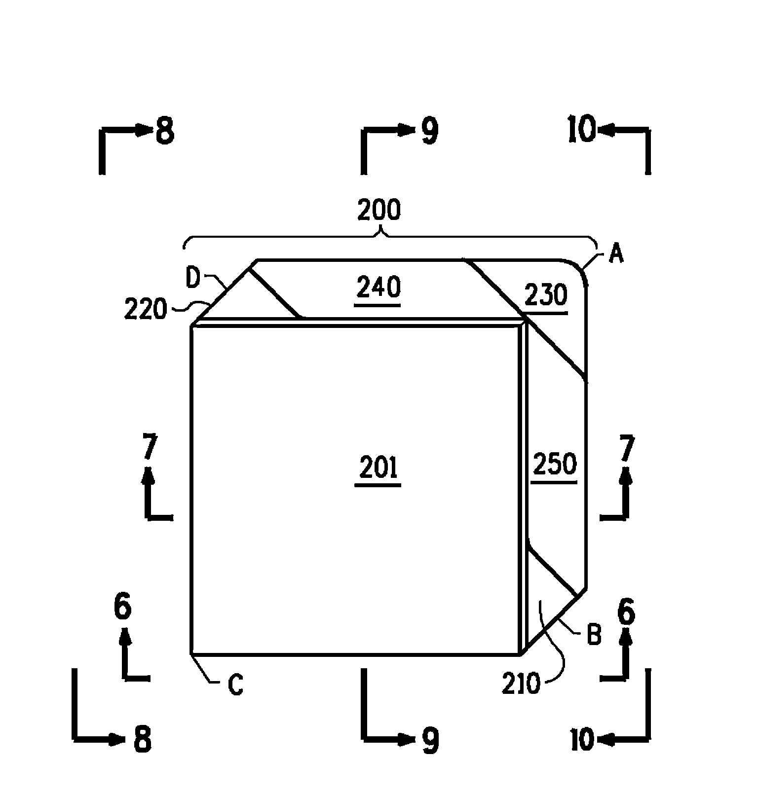
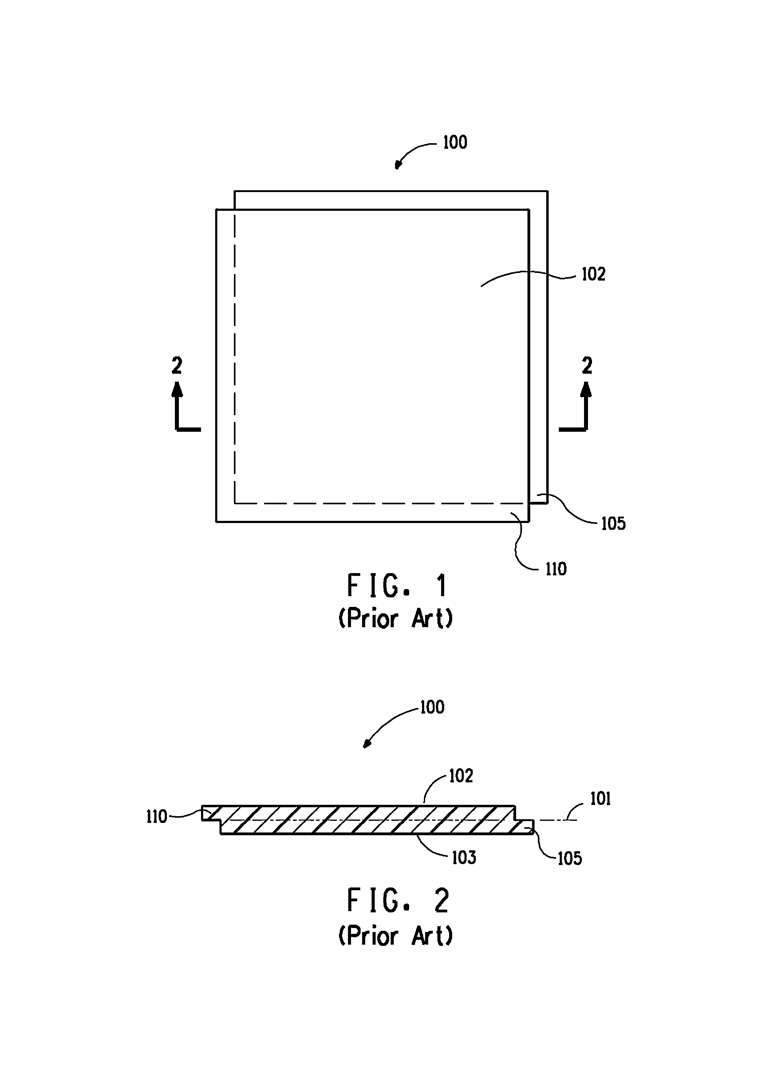
[0038]The subject invention is a building panel with an improved shiplap joint that eliminates the coverage gaps at the corner intersection of building panels. The building panel includes a first face known as a frontface (201) which is exposed to view after installation on the building, which includes an overlap (210-350) portion adapted to overlay the underlap (210-250) of a second face known as backface (301) of one or more improved shiplap building panels laid up in the next higher course of a building wall surface. Prior art shiplap joints use an overlay (110) and underlay (105) that typically mate along the plane of a centerline (101) of the panel. The improved shiplap joint uses backcenterlaps (210, 220) and frontcenterlaps (310, 320) formed along a third plane, or thickness, of material at a center plane of building panels which straddle the plane of the centerline (204). Each pair of backcenterlaps (210, 220) and frontcenterlaps (310, 320) are located at diagonally opposite...


PUM


Abstract

A building panel having improved shiplap joints to provide complete coverage with while providing for panel expansion and contraction. The building panel includes an overlap adapted to overlie a back portion of the backface of one or more panels laid up in the next higher course. Alternate corners of the building panels have centerlaps portions formed at a plane central to the thickness of the building panel that fit between the space defined by the front overlap and the backunderlap. The centerlaps mate to fill gaps that would otherwise open when the building panels expand and contract.

Description

BACKGROUND OF THE INVENTION[0001]1. Field of Invention[0002]The present invention relates to building panels particularly suitable for use as exterior siding on building wall surfaces.[0003]2. Description of the Related Art[0004]In constructing exterior walls of a building, it is known to fasten building panels to a building frame using fasteners or adhesives. Daily and yearly climatic changes require that the building panels have means for expansion and contraction. It is known to use various filler materials such as grout, silicone and recessed filler strips, e.g., metal strips of matching color to resiliently fill the gap between adjacent building panels. Filler materials have the disadvantage of requiring additional labor during application and eventual replacement as the material weathers due to exposure to the elements.[0005]It is also known to use shiplap boards which use shiplap joints to clad the side of a building. Shiplap joints are typically formed by cutting matching ra...

Claims


Application Information

Patent Timeline
Patent Type & Authority Applications(United States)
IPC IPC(8): E04F13/08
CPCE04F13/18E04F13/0889E04F2203/065
Inventor OLSON, BARRY D.PANAGIAN, BARTON
Owner EI DU PONT DE NEMOURS & CO
Why Eureka
Try Eureka