Synthetic resin bottle

Active Publication Date: 2013-07-18
YOSHINO KOGYOSHO CO LTD
View PDF4 Cites 12 Cited by
  • Summary
  • Abstract
  • Description
  • Claims
  • Application Information

AI Technical Summary

Benefits of technology

[0019]This invention having the above-described features has the following effects:
[0020]According to the main feature of this invention, the ribs formed in the flat ring portion serve as the starting points for the flexural deformation of the bottom when there is a decrease in pressure inside the bottle. Because of this role of the ribs, the bottom plate draws upward smoothly, and enables the bottle to perform fully the vacuum absorbing function. Furthermore, because the upward drawing deformation proceeds smoothly, while preventing the foldlines from developing, the bottle can maintain good outer appearance and a high commodity value.
[0021]If the bottle is uncapped and liberated from the reduced pressure state, the entire bottom completely restores its original position from the upward drawing state, and the liquid level goes back to the previous level before the pressure reduction. Therefore, it is easy to avoid the problem that the content fluid may spill out of the neck when one uncaps a bottle to drink the content. Thus, it is possible to increase saf

Problems solved by technology

In that case, it would be difficult to fully satisfy both of the vacuu

Method used


Image

  • Synthetic resin bottle
  • Synthetic resin bottle
  • Synthetic resin bottle

Examples


Embodiment Construction

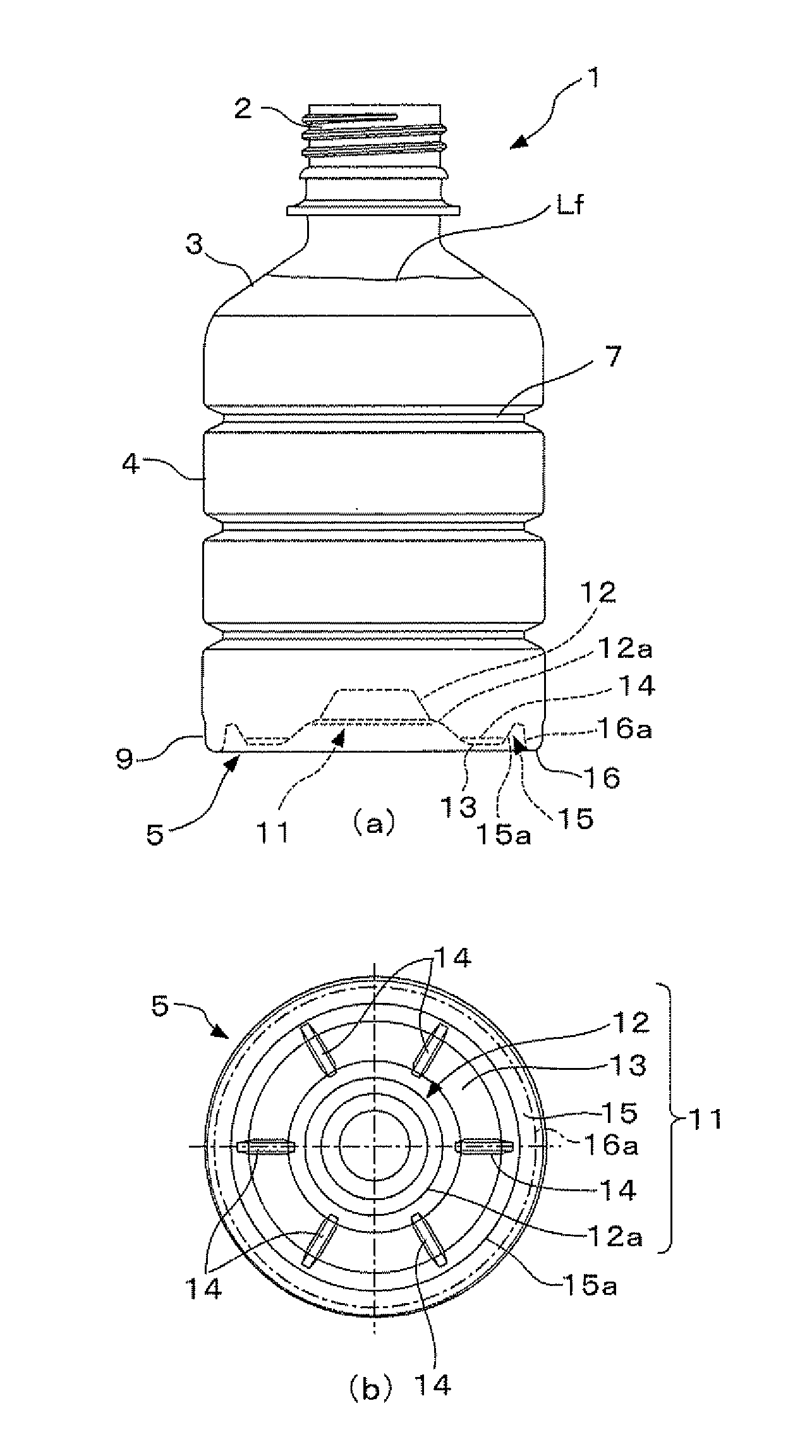
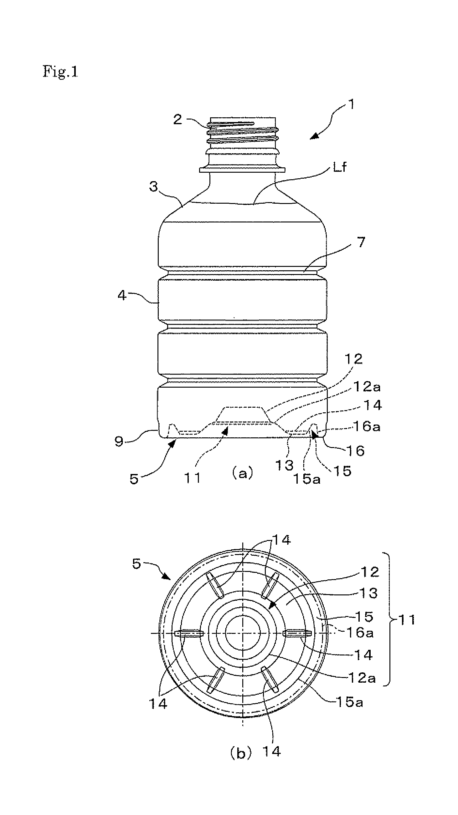
[0030]This invention is further described with respect to a preferred embodiment, now referring to the drawings. FIG. 1(a) is a front view, and FIG. 1(b) is a bottom view, of the synthetic resin bottle in the embodiment of this invention. The bottle 1 has a neck 2, a shoulder 3, a cylindrical body 4, and a bottom 5, and is a biaxially stretched, blow molded product made of a PET resin having a capacity of 350 ml.

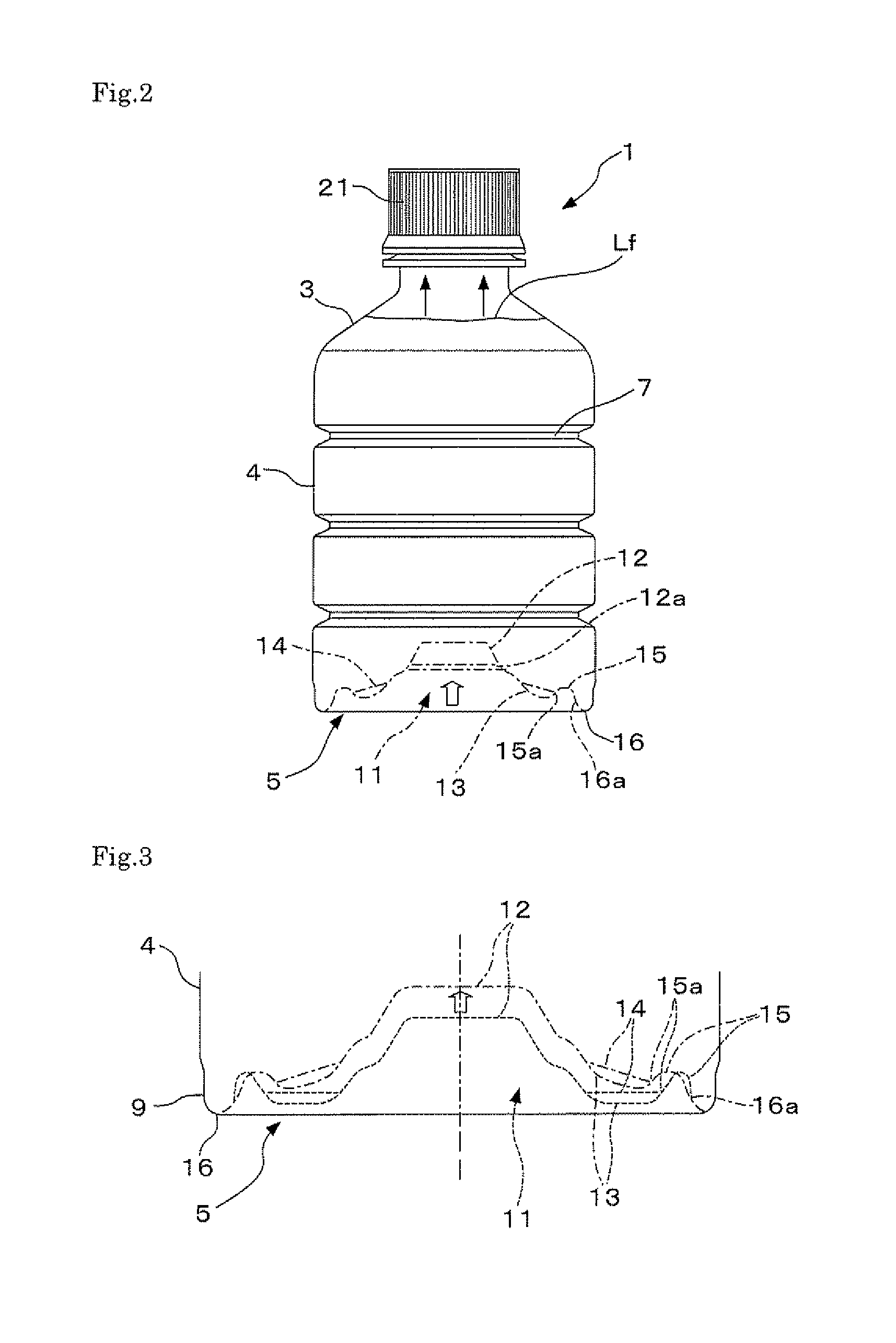
[0031]The body 4 has a plurality of peripheral ribs (three ribs in FIG. 1) to increase surface rigidity so that the bottle has a high ability to retain its shape. A heel wall portion 9 is formed in a curved cylindrical shape at a lower end of this body 4. This heel wall portion 9 has a peripheral ground contact portion 16 on the underside. The bottom 5 is connected to the body 4 by way of this heel wall portion 9, which is disposed in an outermost peripheral area of the bottom 5.

[0032]A sunken bottom portion 11 is formed in the bottom 5. Starting from an unmoving end 16a dis...


PUM


Abstract

A biaxially stretched, blow molded synthetic resin bottle has a bottom including a sunken bottom portion, and deforms as it draws upward in a direction of the bottle inside and includes a ring groove formed by being successively connected to an inner peripheral edge of a ground contact portion disposed at the foot of an outer peripheral wall of the bottom, a central concave portion disposed at a center of the bottom, and a flat ring portion disposed between an inner peripheral edge of the ring groove and the central concave portion, wherein the sunken bottom portion includes a plurality of short slim ribs disposed at several points of the flat ring portion.

Description

TECHNICAL FIELD[0001]This invention relates to a synthetic resin bottle, especially to the one provided with a body having high shape-retainability and with a bottom allowing reduced pressure to be absorbed by the deformation of a bottom plate, which draws upward when the pressure drops inside the bottle.BACKGROUND ART[0002]Biaxially stretched and blow-molded bottles made of polyethylene terephthalate (hereinafter referred to as “PET”), the so-called PET bottles, have high levels of transparency, mechanical strength, heat resistance, and gas barrier property, and up to now, have been in wide use as the containers for various beverages. Conventionally, what is called hot filling is utilized as a method of filling the PET bottles with content fluids, e.g., juices, teas, and the like, which require pasteurization. This involves filling the bottle with a content fluid at a temperature of about 90 degrees C., sealing the bottle with a cap, and cooling the bottle. This process causes the ...

Claims


Application Information

Patent Timeline
IPC IPC(8): B65D23/00
CPCB65D1/0261B65D1/0276B65D23/001B65D79/005B65D79/0081B65D1/02
Inventor KURIHARA, GORO
Owner YOSHINO KOGYOSHO CO LTD
Why Eureka
Try Eureka