
Method and device for forcibly inserting drop into compression molding machine, and molding die follow-up type method and device for supplying drop

a technology of compression molding machine and drop, which is applied in the direction of dough shaping, manufacturing tools, applications, etc., can solve the problems of inability to perform serial production, inability to obtain precise preforms, etc., and achieve the effect of simple configuration, accurate and rapid insertion of drop into female, and simple operation

Inactive Publication Date: 2013-07-18
TOYO SEIKAN GRP HLDG LTD
View PDF2 Cites 1 Cited by
  • Summary
  • Abstract
  • Description
  • Claims
  • Application Information

AI Technical Summary

Benefits of technology

[0012]The present inventors looked from various angles repeatedly and continued experimental consideration with the aim of developing an additionally modified technique to insert the drops more accurately and rapidly, while preventing the drops from displacement from the required positions in the female concaves and drop, even when the difference between maximum external diameter of the drops and the inner diameter of the female concaves is smaller or even when the moving rate of the drop-holding mechanism is raised more, or even the molding cycle is performed much faster by raising the rotation rate of the rotary-type compression molding machine, and in seeking for novel modified technique in various ways such as a molding supply of drops, a drop-holding mechanism, a drop and insertion means of the drop, a molding cycle and so on. In consequence, the present inventors found the technique with which the drop insertion can be performed more accurately and rapidly.
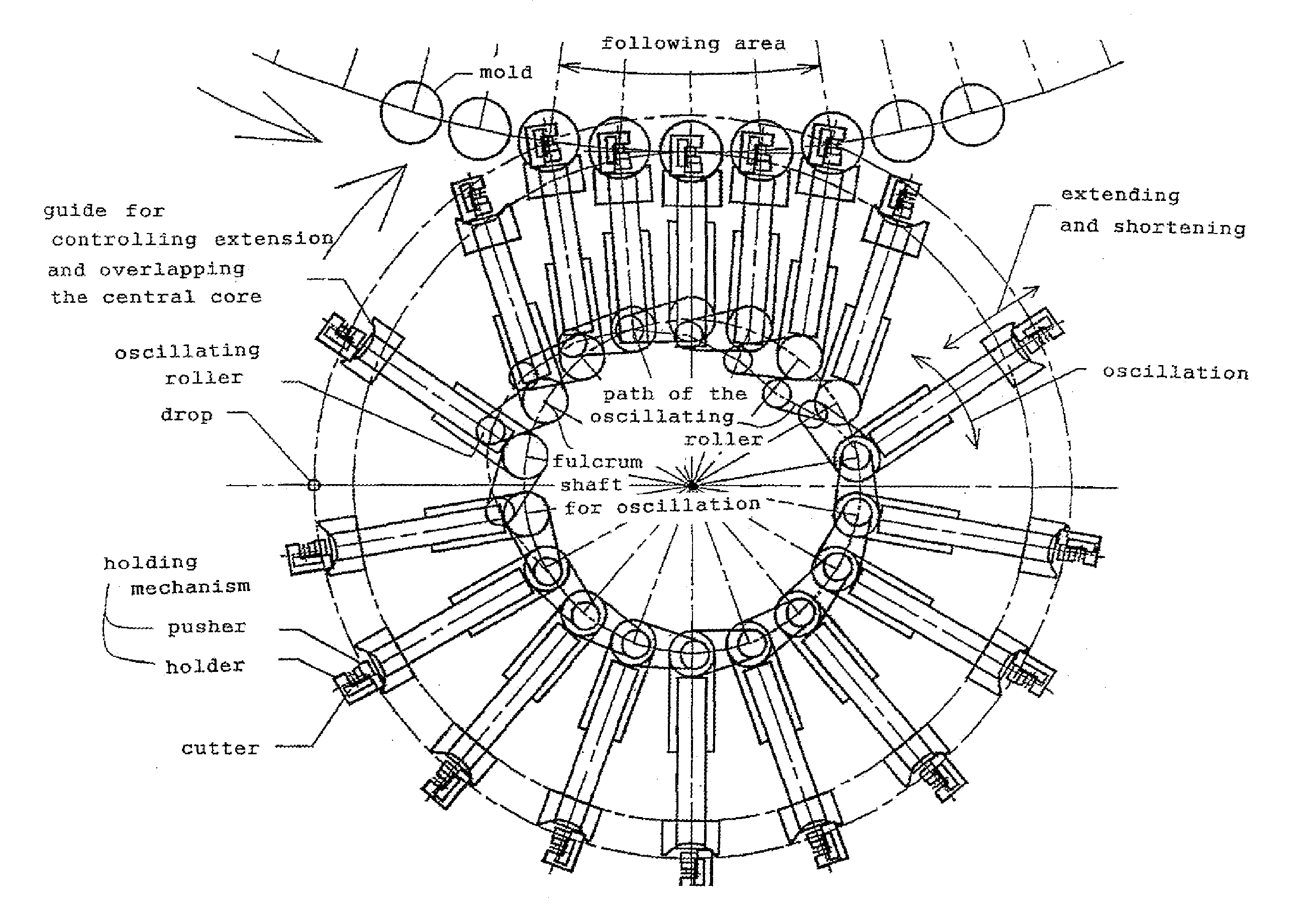
[0013]In this novel technique, as the result of the consideration of the means for contriving drop of the drops wherein the drops are dropped in a different way than the conventional free drop, the present inventors could achieve the novel recognition that forcible drop of the drops instead of free fall settles the direction of drop forcibly, which allows accurate and rapid insertion of the drops into female concaves. Specifically, the means uses a technique for dropping drops which drops at an accelerating speed or at a constant speed by lowering the holding mechanism suddenly or at a constant speed with the use of acceleration or law of inertia, when the holding function of the holding mechanism of the drop is released to drop the drops. The technique is to be the first basic constituent of the present invention, which only requires attachment of a driven-type lift of the holding mechanism. Thus, the additional instrument may have a simple configuration and cost low.
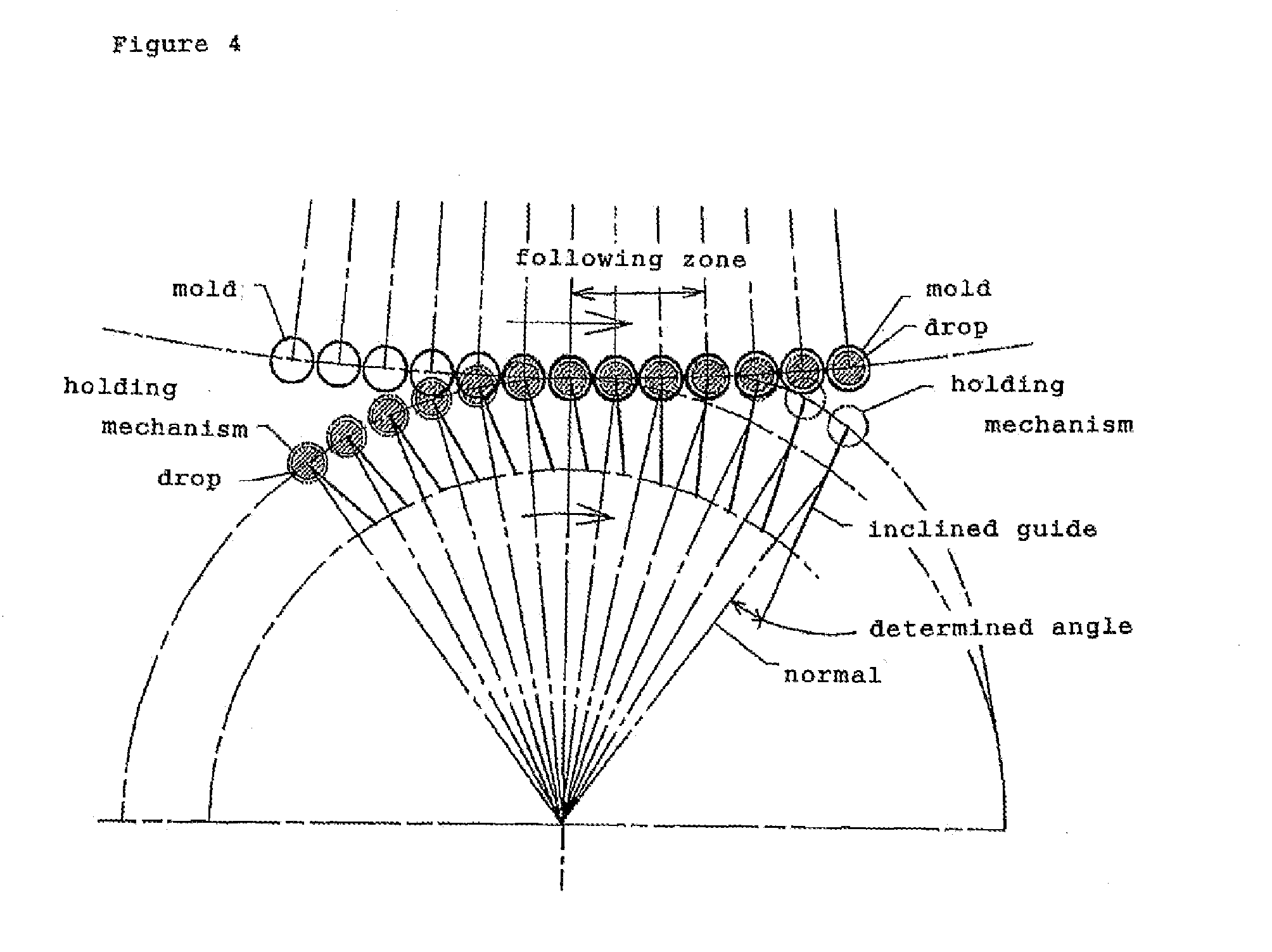
[0014]Further, the present inventors conceived that the drops can be inserted more accurately, when the drops are dropped in the overlapped paths in this novel technique, since a rotation path of a rotary-and movable type drop supply having many holding mechanisms overlaps with a rotation path of a rotary-and movable type having many molds in a rotary-type compression molding machine. Still further, in the process of repeating discussion and experiments for seeking development of additionally modified technique, in order to supply the drops more accurately rapidly and simply, the present inventors considered carefully: that applying the technique for making the movement of the holding mechanism follow that of the female mold by overlapping these paths of rotation is very effective in even more accurate and rapid insertion of the drop; that using the technique by the innovative idea causes less displacement of the drop-holding mechanism from the required positions in the female concaves, while dropping the drop by releasing the drop-holding of the holding mechanism can realize insertion of the drop more completely accurately at the time point when the position of the holding mechanism overlap with that of the female mold during the time when the rotation path of the holding mechanism overlaps with that of the female mold by making the movement of the holding mechanism follow, even if time lag may occur regarding the positions of the holding mechanism and the female mold on the overlapping rotation paths; and further a windowtime generated by the overlapping paths may also ensure accuracy of insertion of the drops complementarily. From this consideration, the present inventors could obtain finding as innovative and novel creative technique. The present invention was thus created.
[0015]The specific technique is to be the second basic constituent of the present invention, in which the drop point of the drop by releasing the drop-holding function of the holding mechanism overlaps or nearly overlaps with the position of the passage of the female mold, by realizing overlap of paths of rotary moving of the holding mechanism (more specifically the holding part of the drop) and that of the molding die and making the movement of the holding mechanism follow that of the molding die (or, by making the movement of the molding die follow that of the holding mechanism, vice versa) as mentioned above. This novel technique can realize insertion of the drop completely accurately and rapidly by a simple means, while preventing the drop from displacement from the required position in the female concave and drop even when the difference between the maximum external diameter of the drop and the inner diameter of the female concave is smaller or even when the moving rate of drop-holding mechanism is raised more. Further, the drop can be inserted completely or almost completely accurately even when the molding cycle is performed much faster by raising the rotation rate of the rotary-type compression molding machine in order to increase production efficiency.

Problems solved by technology

On the other hand, compression molding machines are traditionally known as molding devices which enable molding at relatively lower cost compared with that in molding by injection molding machines and at relatively lower temperature, while there was a defect that they cannot perform serial production.
Without accuracy, it is impossible to obtain precise preforms since a part of drops overbrim the cavity.
Therefore, performing continuous supply and insertion of the drop more rapidly and accurately has become an important problem in continuous production device of preforms by compression molding machines, however, disclosure of the modified technology aiming at solution of this problem has not seldom been suggested yet, and there are only a few disclosures, e.g. that of modified device wherein a synthetic-resin guiding means having a reverse frustum configuration and having a guiding opening at the drop point of the drop, is provided (see, Japanese Laid-Open Patent Application No. 2000-280248).

Method used

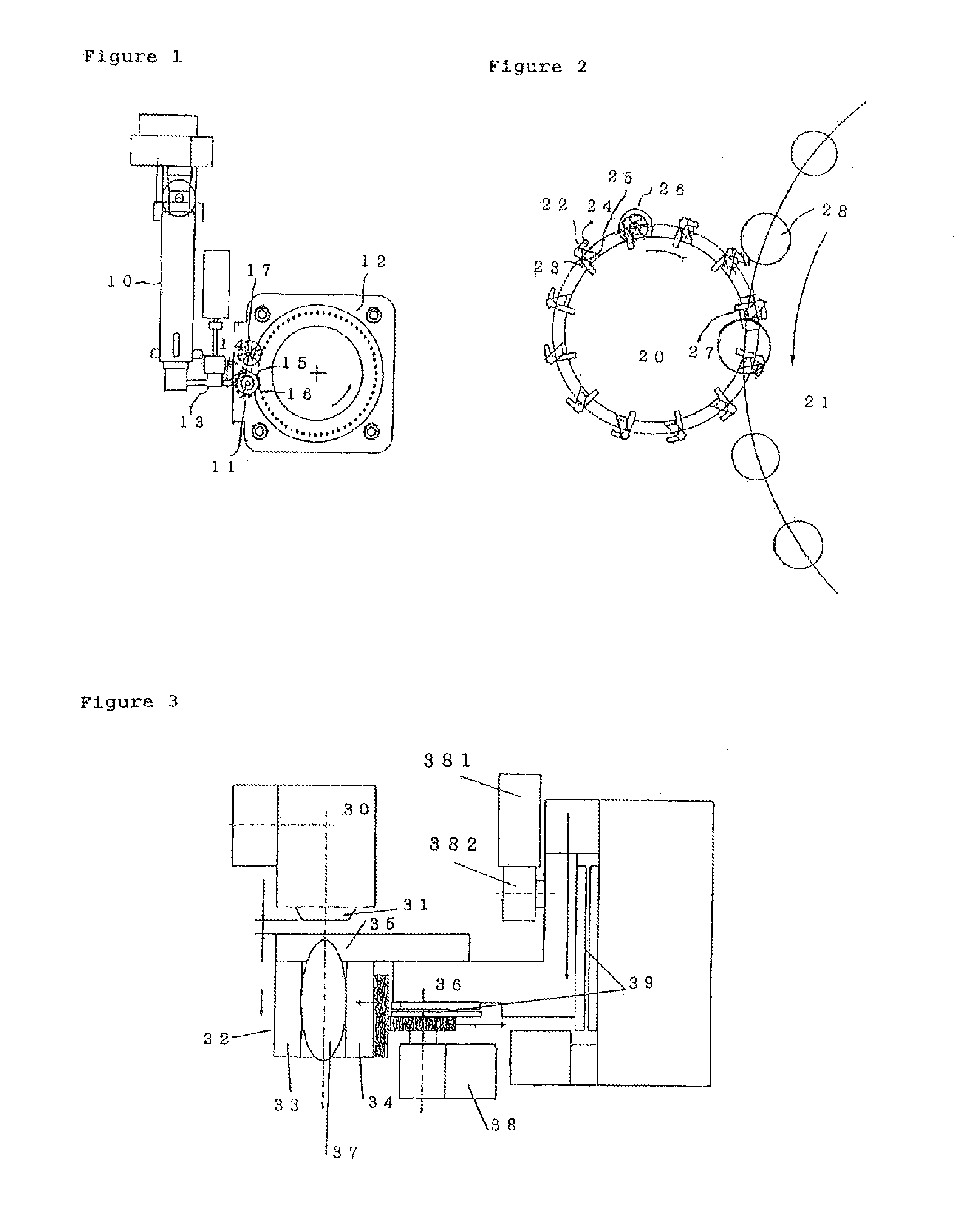

Image

  • Method and device for forcibly inserting drop into compression molding machine, and molding die follow-up type method and device for supplying drop
  • Method and device for forcibly inserting drop into compression molding machine, and molding die follow-up type method and device for supplying drop
  • Method and device for forcibly inserting drop into compression molding machine, and molding die follow-up type method and device for supplying drop

Examples


Embodiment Construction

[0030]The preferred embodiments of the present invention are specifically described in detail referring to each of the drawings presenting prototypes of the embodiments.

(1) Molding System of the Present Invention

[0031]The method and device of the molding system of the present invention wherein drops are accurately, rapidly, and continuously supplied and inserted into female molds of a compression molding machine, and it is preferably used for molding preforms for manufacturing containers by blow molding following compression molding or the like.

[0032]The basic system of the present invention is a method or device for forcibly inserting drops of a molding material into concaves of molding female dies in a compression molding machine, wherein molten synthetic resin extruded from an extrusion opening formed at the edge of an extrusion die head is formed into a determined quantity of drops by holding and then cutting or cutting and then holding by a holding mechanism and a cutting membe...


PUM

PropertyMeasurementUnit
distanceaaaaaaaaaa
areaaaaaaaaaaa
accelerating speedaaaaaaaaaa

Abstract

A method and device for continuously supplying molten synthetic resin drops into female moldings which are rotatingly movable for manufacturing moldings, wherein synthetic resin in molten condition extruded from an extrusion opening is cut by a cutter attached to a holding mechanism to form the molten resin into drops in a determined quantity, the drops are held and conveyed by the holding mechanism, and the drops are forcibly inserted and supplied into the concaves of the female moldings. At that time the holding mechanism on the rotary-and movable type drop supply is made to approach the rotating molding die and the rotation path of the holding mechanism is made to overlap with that of the molding die within a determined area to make the movement of the holding mechanisms follow that of the molding die.

Description

CROSS-REFERENCE TO RELATED APPLICATIONS[0001]This is a divisional application of U.S. patent application Ser. No. 10 / 564,445, filed on Aug. 17, 2006, which is a 371 of International Application No. PCT / JP2004 / 010263, filed on Jul. 13, 2004, which claims the benefit of priority from the prior Japanese Patent Application Nos. 2003-196830, filed on Jul. 14, 2003 and 2003-368001 filed on Oct. 28, 2003, the entire contents of which are incorporated herein by references.TECHNICAL FIELD[0002]The present invention relates to a method and device for supplying molding materials, i.e. drops (lumps of the molten synthetic resin) into molding dies continuously in a compression molding machine for synthetic resin, and the present invention specifically relates to a method and device for supplying drops in order to continuously, accurately and rapidly supply molten drops extruded from an extrusion die head into female cavities (female concaves) of a compression molding machine when preforms for mo...

Claims


Application Information

Patent Timeline
Patent Type & Authority Applications(United States)
IPC IPC(8): B29B11/02B29C31/04B29C43/08B29C43/34
CPCB29C31/048B29C43/08B29C43/34B29B11/02B29C2043/3411B29C2043/3466B29C2043/3494B29C2043/3288B30B11/12B29C43/02B29C31/04B29B11/10B29B11/12
Inventor NEMOTO, SATORUTAKANO, SHOICHIROHASHIMOTO, HIROYUKI
Owner TOYO SEIKAN GRP HLDG LTD
Learn More