Waveguide structure for a contactless connector

a contactless connector and waveguide technology, applied in waveguide horns, waveguide type devices, one-port networks, etc., can solve problems such as complex translation, signal and performance decline, and problems such as problems, to extend the propagation distance of rf signals, and enhance communication links.

Inactive Publication Date: 2013-07-18
TE CONNECTIVITY CORP
View PDF3 Cites 13 Cited by
  • Summary
  • Abstract
  • Description
  • Claims
  • Application Information

AI Technical Summary

Benefits of technology

[0008]Optionally, the waveguide structure may include a waveguide, a first waveguide module at one end of the waveguide and a second waveguide module at an opposite end of the waveguide. The waveguide structure may include at least one passive component. Optionally, the passive component may enhance the communication link between the first and second communication chips. The passive component may redirect the RF signal. The passive component may collect the RF signal. The passive component may reflect the RF signal in a general direction. The passive component may extend the propagation distance of the RF signal. The passive component may change the propagation direction of the RF signal, change the propagation mode of the RF signal, change the polarization of the RF signal and / or combines multiple modes of RF signals. The passive component and / or the waveguide may shield the RF signal from interfering signals.

Problems solved by technology

While the chips can be separated longitudinally within certain limits with little or no degradation in performance, beyond such limits the signal and performance are diminished.
Problems arise when complex translation is required.
For example, translation in more than one direction is problematic and leads to signal degradation and / or transmission failure.

Method used


Image

  • Waveguide structure for a contactless connector
  • Waveguide structure for a contactless connector
  • Waveguide structure for a contactless connector

Examples


Embodiment Construction

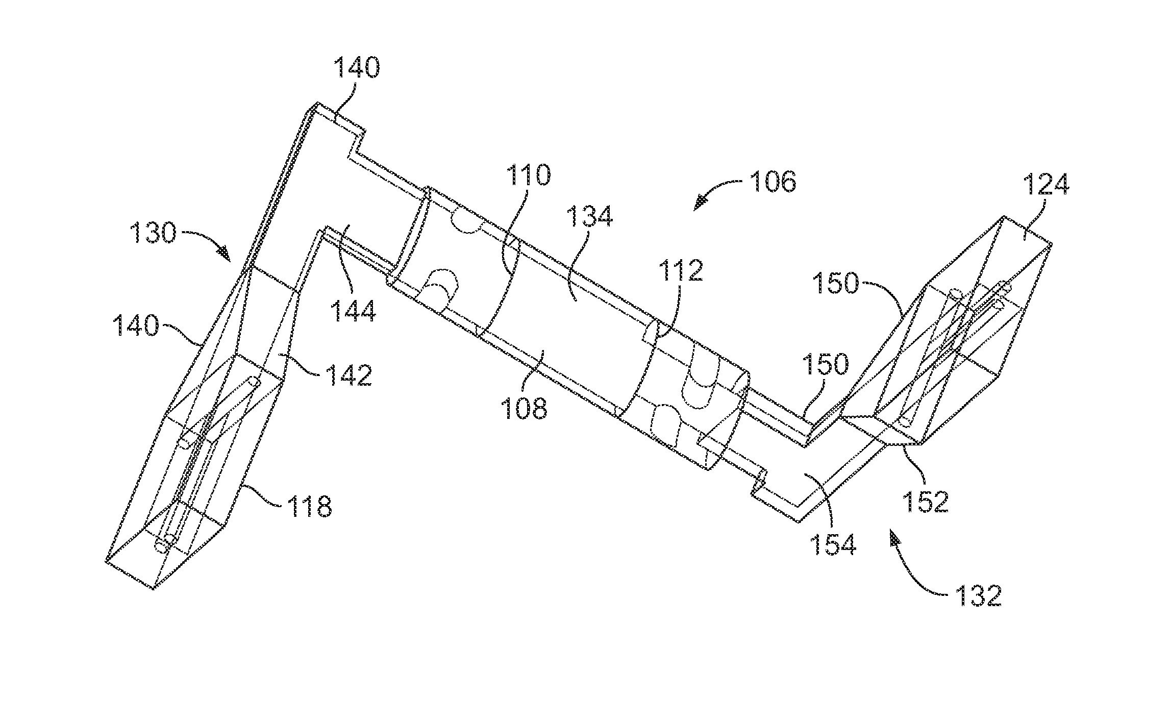
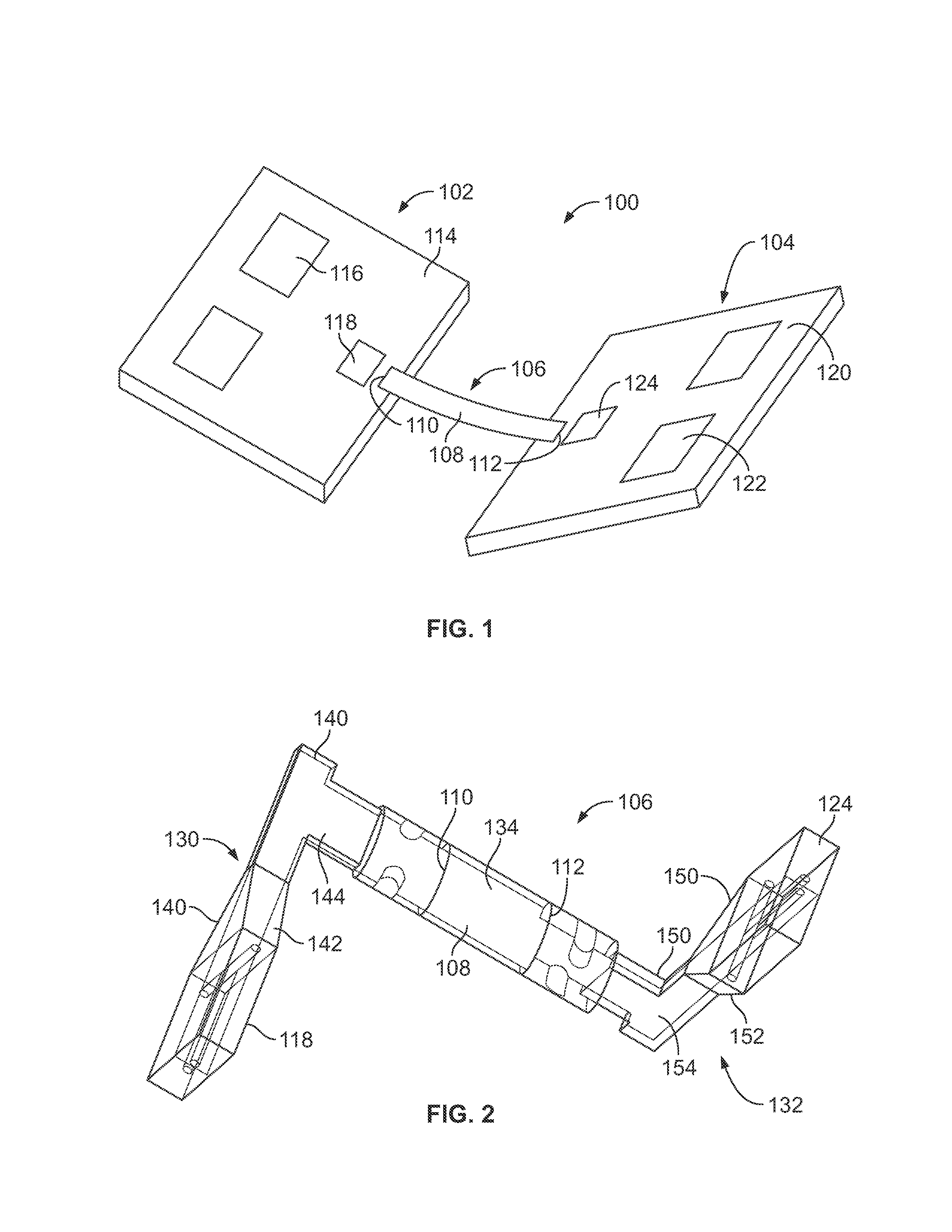
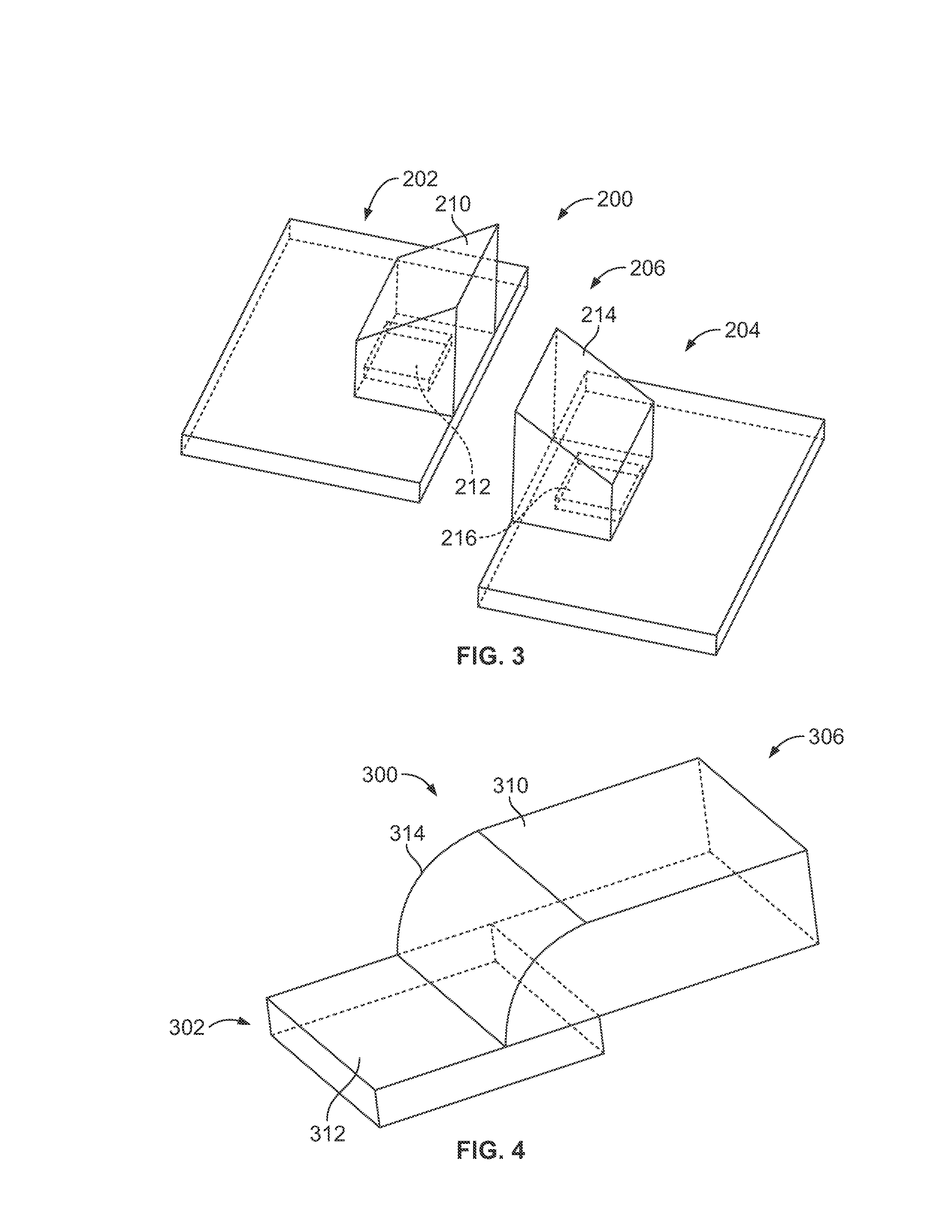
[0018]Embodiments described herein provide a contactless connector having two modules that form a data link. A waveguide structure is provided that connects the two modules for guiding and shielding the data link. The waveguide structure directs the energy along a particular path to enhance the communication link between the two modules. The modules may include RF transmitters and receivers, which may be chips, for the purpose of communicating wirelessly with similar chips and transmitter / receivers. The transmission and reception of RF signals to and from these chips is dependent on the relative position of the chips as well as the positions and orientation of the waveguide structure and / or the transmitters, receivers, antenna structures, groundplanes and other structures contained within the contactless connector.

[0019]Embodiments described herein provide a waveguide structure that is external to the chips. The waveguide structure may be used to collect, re-direct, extend the propa...


PUM


Abstract

A contactless connector includes a first communication chip configured to at least one of transmit and receive wireless RF signals, a second communication chip configured to at least one of transmit and receive wireless RF signals, and a waveguide structure between the first and second communication chips. The waveguide structure conveys RF signals between the first and second communication chips.

Description

CROSS REFERENCE TO RELATED APPLICATIONS[0001]This application claims the benefit of U.S. Provisional Application No. 61 / 587,972 filed Jan. 18, 2012, the subject matter of which is herein incorporated by reference in its entirety.[0002]This application discloses subject matter that relates to subject matter described in U.S. patent application Ser. No. 13 / 336,705 filed Dec. 23, 2011, titled CONTACTLESS CONNECTOR, the subject matter of which is herein incorporated by reference in its entirety.BACKGROUND OF THE INVENTION[0003]The subject matter herein relates generally to contactless connectors that provide contactless data transmission at short range using RF energy and waveguide structures for such contactless connectors.[0004]Contactless connectors typically include a transmitter chip and a receiver chip. A data stream is furnished to the transmitter chip, which produces a modulated RF signal, such as at 60 GHz. That signal is propagated a short distance to the receiver chip, which ...

Claims


Application Information

Patent Timeline
Patent Type & Authority Applications(United States)
IPC IPC(8): H01P5/00H01P1/16H01P1/06
CPCH04B5/0031H01Q13/02H01Q1/2283H01P1/06
Inventor MCCARTHY, SEAN PATRICKJARRETT, STEVEN ALANBISHOP, BRUCE FOSTERHILTY, ROBERT DANIEL
Owner TE CONNECTIVITY CORP
Why Eureka
Try Eureka