High speed communication

a high-speed communication and data communication technology, applied in the field of data communication links, can solve the problems of increasing bulky copper cable wires, consuming relatively high power, and unattractive overall cable package, and achieve the effect of enhancing bandwidth

Inactive Publication Date: 2011-06-23
QUANTUM ELECTRO OPTO SYST
View PDF31 Cites 48 Cited by
  • Summary
  • Abstract
  • Description
  • Claims
  • Application Information

AI Technical Summary

Benefits of technology

[0016]Another embodiment of this form of the invention has application for use in improving a communication link between a first location and a second location, the first location having an electrical driver circuit that receives input data to be communicated, and the second location having an electrical receiver circuit for producing output data representative of said input data, said link being adapted to have an electrically conductive cable coupled between said electrical driver circuit and said electrical receiver circuit. A method is set forth including the following steps: removing said electrically conductive cable; providing a tilted charge light emitting device at said first location and coupled with said driver circuit such that the light produced by said tilted charge light-emitting device is a function of said input data; providing an optical fiber between said first and second locations; coupling light from said tilted charge light emitting device into said optical fiber; and providing, at said second location, a photodetector coupled with said optical fiber and with said receiver circuit; whereby electrical signals representative of said input data are output from said receiver circuit.
[0017]In accordance with a further form of the invention, a technique is set forth for high speed communication of input information, including the following steps: producing a pair of phase-opposed electrical signals representative of said input information; providing a three terminal tilted-charge light-emitting device in a common collector configuration; applying one of said phase-opposed signals to a base-collector input of said tilted charge light-emitting device and the other of said phase opposed signals to an emitter-collector input of said tilted charge light-emitting device, to produce an optical signal as a function of both of said phase-opposed signals; communicating said optical signal to a receiving location; and receiving said optical signal at said receiving location and converting said optical signal to an output electrical signal representative of said input information. The optical signal, which is a function of both of said phase-opposed signals, is proportional to the sum of the absolute values of the phase-opposed signals.
[0018]An embodiment of this form of the invention further comprises the step of applying first and second equalizer functions to respective ones of said pair of phase-opposed electrical signals before applying said phase-opposed signals to said tilted charge light-emitting device. In this embodiment, the step of applying said first equalizer function includes applying a first type of frequency filtering, and said step of applying said second equalizer function includes applying a second type of frequency filtering that is different than said first type of frequency filtering. The first type of frequency filtering can comprise low pass filtering and said second type of frequency filtering can comprise high pass filtering, and bandwidth enhancement can accordingly be achieved.

Problems solved by technology

Therefore, as the speed of data rate increases to the presently used 3.4 Gbits / s per channel (HDMI), or even 4.8 Gbit / s (for USB 3.0), copper cable wires have become increasingly bulky and expensive, and the overall cable package is unattractive even for transmission distances of less than 5 meters.
In addition to the limitations and disadvantages already mentioned, the copper link consumes relatively high power, can require expensive EMI shielding, and involves use of substantial amounts of non-recyclable materials.
An optical link can eliminate certain copper link disadvantages, but at a higher initial cost and higher power consumption.
However, these techniques require additional feedback control integrated circuitry (ICs) and additional drivers (optical drivers) that consume substantial power and significantly add to cost.
As above-indicated, this additional circuitry is expensive and consumes relatively high power.

Method used


Image

  • High speed communication
  • High speed communication
  • High speed communication

Examples


Embodiment Construction

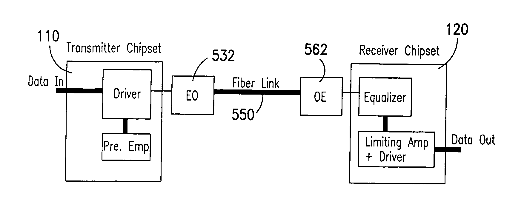
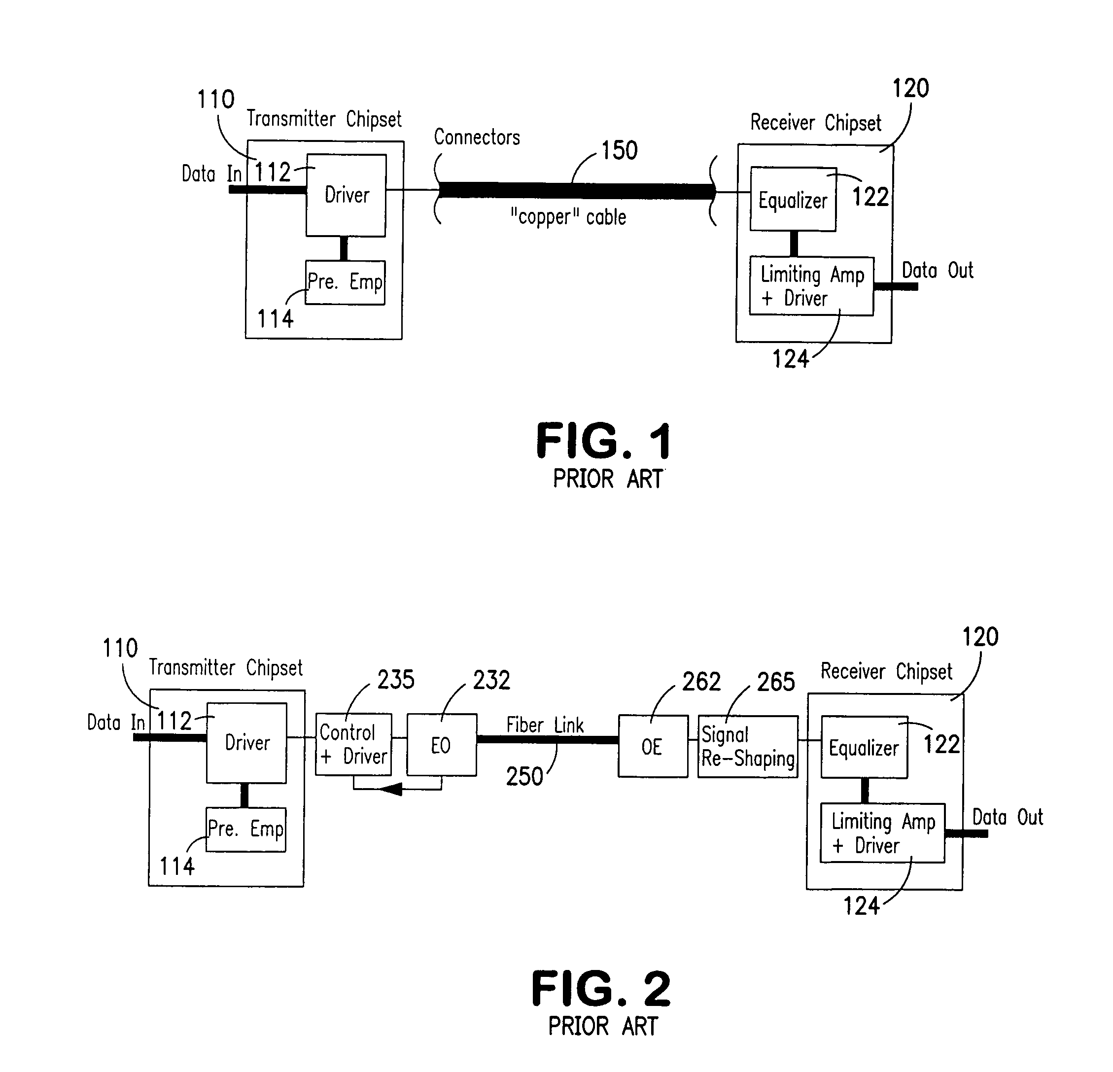
[0031]FIG. 5 is a diagram of an idealized fiber link for connection between a transmitter chipset 110 (as in FIG. 1) and a receiver chipset 120 (as also in FIG. 1) of the copper link illustrated in FIG. 1, but with the copper cable replaced by fiber link 550, an electrical-to-optical (EO) converter 532, and an optical-to-electrical (OE) converter 562. As described, for example, in conjunction with FIG. 2, however, substantial additional circuitry is presently required in conjunction with the conversion from a copper cable to a fiber link. A challenge hereof was to eliminate the need for some or all of the additional circuitry, and also to have the EO and OE converters powered by existing copper transmitter and copper receiver chipsets (and not externally powered) and be matched directly to existing built-in pre-emphasis and copper equalizers in the existing chipsets without the addition of the costly interface circuitry that is presently needed. Ideally, the EO-fiber cable-OE link s...


PUM


Abstract

The disclosure has application for use in establishing a communication link between a first location and a second location, the first location having an electrical driver circuit that receives input data to be communicated, and the second location having an electrical receiver circuit for producing output data representative of the input data. The method includes the following steps: providing a tilted charge light emitting device at the first location and coupled with the driver circuit such that the light produced by the tilted charge light-emitting device is a function of the input data; providing an optical fiber between the first and second locations; coupling light from the tilted charge light emitting device into the optical fiber; and providing, at the second location, a photodetector coupled with the optical fiber and with the receiver circuit; whereby electrical signals representative of the input data are output from the receiver circuit.

Description

PRIORITY CLAIMS[0001]Priority is claimed from U.S. Provisional Patent Application No. 61 / 280,822, filed Nov. 9, 2009, and from U.S. Provisional Patent Application No. 61 / 403,750, filed Sep. 21, 2010, and both of said Provisional Applications are incorporated herein by reference.FIELD OF THE INVENTION[0002]This invention relates to the field of data communication links, and also to improvement of existing so-called copper communication links, and to improved electro-optical communication links and techniques, and also to improved electro-optical differential signaling techniques.BACKGROUND OF THE INVENTION[0003]Cable links commonly serve the functions of transmitting electrical power and transmitting electrical signals. When used to transmit signals; the cable links are called data interconnects. When the cable link media is made of an electrically conductive material, it is conventionally called a copper data interconnect, or copper link, whether the metal is strictly copper, or ano...

Claims


Application Information

Patent Timeline
Patent Type & Authority Applications(United States)
IPC IPC(8): H04B10/00
CPCH04B10/2504H04B10/12H04B10/25759H04B10/25891H04B3/04H04B10/25
Inventor WALTER, GABRIEL
Owner QUANTUM ELECTRO OPTO SYST
Why Eureka
Try Eureka