Subsea Cable Termination Assembly, Subsea Connector and Method

a technology of subsea cable and connector, which is applied in the direction of mechanical equipment, coupling device connection, instruments, etc., can solve the problems of limited physical length of communication links, relatively complex connectors, and high cost of design and production. achieve the effect of reducing cost and high bandwidth

Active Publication Date: 2014-04-03
SIEMENS ENERGY AS
View PDF7 Cites 23 Cited by
  • Summary
  • Abstract
  • Description
  • Claims
  • Application Information

AI Technical Summary

Benefits of technology

[0030]A further embodiment provides a subsea cable assembly that includes a subsea cable including one or more optical fibers for data transmission and a subsea connector in any of the above outlined configurations. The cable termination assembly of the subsea connector terminates the subsea cable at an end of the subsea cable and provides an optical connection of the one or more optical fibers to the media converter. Such subsea cable assembly may enable an optical transmission of data at relatively high bandwidth over considerable distances (e.g., in excess of 1 kilometer). For example, such subsea cable assembly may enable a communication between different Christmas trees of a subsea installation. It is thus not necessary to have at each Christmas tree an umbilical to a topside installation, which may result in considerable cost reductions, since umbilicals may be very expensive. With the subsea cable assembly, advantages similar to the ones outlined further above may be achieved.

Problems solved by technology

Although such type of communication link may achieve relatively high bandwidth (e.g., 10 Mbps, 100 Mbps or even 1 Gbps), such types of communication links are limited in physical length.
In general, communication using such type of technology is thus limited to subsea control modules of the same Christmas tree.
Such connectors are relatively complex and cost intensive to design and produce.

Method used


Image

  • Subsea Cable Termination Assembly, Subsea Connector and Method
  • Subsea Cable Termination Assembly, Subsea Connector and Method
  • Subsea Cable Termination Assembly, Subsea Connector and Method

Examples


Embodiment Construction

[0042]In the following, embodiments illustrated in the accompanying drawings are described in more detail. The following description is only illustrative and non restrictive. The drawings are only schematic representations, and elements in the drawings are not necessarily to scale with each other.

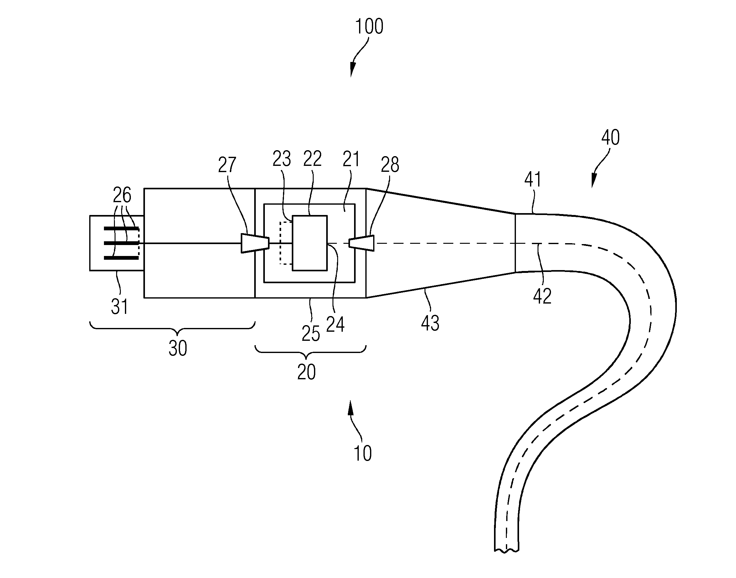
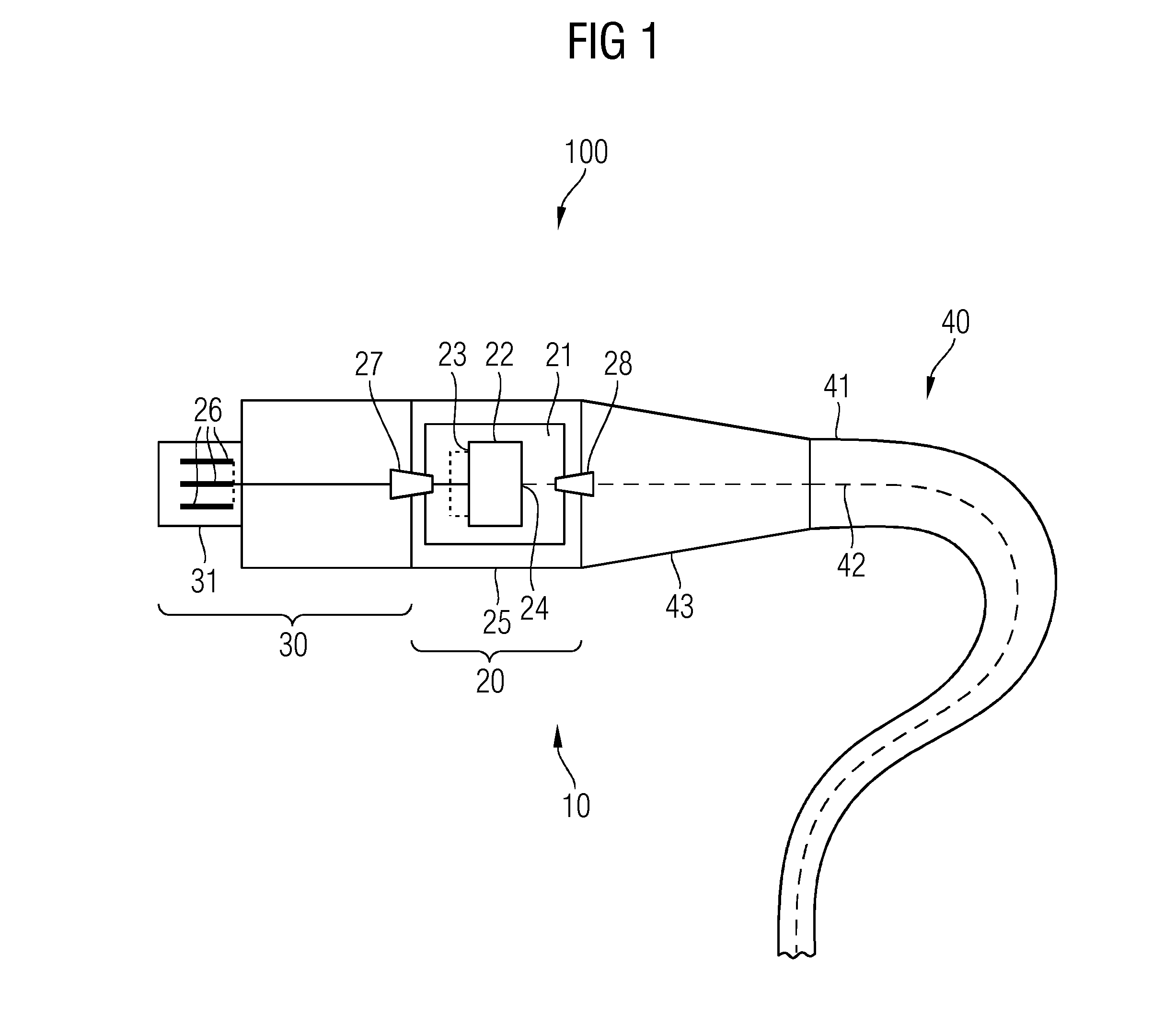
[0043]FIG. 1 shows one embodiment of a subsea cable assembly 100 including a subsea connector 10 and a subsea cable 40. The subsea connector 10 includes a subsea cable termination assembly 20 and a connector portion 30. Although the subsea cable termination assembly 20 and the connector portion 30 are shown as separate elements, the subsea cable termination assembly 20 and the connector portion 30 may in other embodiments be parts of a subsea connector and may not be separable.

[0044]The subsea connector 10 may be implemented as a male or a female connector. In the embodiments described hereinafter, the subsea connector 10 is a wet mateable connector, although implementations as a dry mate c...


PUM


Abstract

A subsea cable termination assembly for a subsea cable that includes an optical fiber for data transmission is provided. The subsea cable termination assembly includes a chamber that has a liquid tight seal against an ambient medium surrounding the subsea cable termination assembly, and a media converter arranged in the chamber. The media converter includes an optical interface adapted to be connected to an optical fiber of the subsea cable, and an electrical interface. The subsea cable termination assembly also includes an electric contact arranged outside the chamber and electrically connected to the electrical interface of the media converter arranged inside the chamber.

Description

[0001]This application claims the benefit of EP 12186843.4, filed on Oct. 1, 2012, which is hereby incorporated by reference.FIELD[0002]The present embodiments relate to a subsea cable termination assembly for a subsea cable.BACKGROUND[0003]Due to the increasing energy demands, offshore oil and gas production is moving into deeper waters. For providing an efficient and secure production, processing facilities are being installed at the ocean floor. Such subsea installations may include a range of components, including pumps, compressors and the like, as well as a power grid for operating the components. The power grid may, for example, include a subsea transformer, subsea switchgear and subsea variable speed drives. The components of the subsea installation are to be protected from the surrounding seawater, in which pressures of 300 bar or more may prevail (e.g., at installation depths of 3,000 m or more).[0004]Components of such subsea installations may include electronic equipment...

Claims


Application Information

Patent Timeline
Patent Type & Authority Applications(United States)
IPC IPC(8): G02B6/42H04B10/80F16L1/12
CPCG02B6/4278H04B10/80F16L1/12G02B6/3816H02G15/14H01R13/523G02B6/4427G02B6/4428
Inventor JAMTVEIT, ENDRE FOSSOVILLMARK, TROND HOLGER
Owner SIEMENS ENERGY AS
Why Eureka
Try Eureka