Cartridge, printing material supply system, and printing apparatus

a technology of printing material supply system and printing apparatus, which is applied in the direction of printing, etc., can solve the problems of dust pulling therein, and insufficient contact between the apparatus side terminal group and the cartridge side terminal group

Active Publication Date: 2013-07-18
SEIKO EPSON CORP
View PDF2 Cites 42 Cited by
  • Summary
  • Abstract
  • Description
  • Claims
  • Application Information

AI Technical Summary

Benefits of technology

[0014]An advantage of some aspects of the invention is that it provides a technique of properly achieving contact between a cartridge side terminal group and an apparatus side terminal group.

Problems solved by technology

However, in the techniques of JP-A-2003-341100 and JP-A-2007-230249, due to manufacturing errors in the cartridge mounting unit or the cartridge, there is a possibility that the cartridge side terminal group and the apparatus side terminal group may not come into contact with each other so as to be electrically connected.
Therefore, errors in the shape of the recessed portion occur due to design errors in the cartridge, and thus there is a possibility that contact between the cartridge side terminal group and the apparatus side terminal group may not be properly achieved.
In addition, in the technique described above, there is a possibility that the apparatus side terminal group may rub against the side surface of the recessed portion or the cartridge side terminal group between when the cartridge is inserted into the cartridge mounting unit and when the cartridge is mounted to the cartridge mounting unit.
In addition, there may be cases where dust is pulled therein due to static electricity generated by rubbing of the apparatus side terminal group against the side surface of the recessed portion or the like.
When shavings, dust, and the like are present at the periphery of the apparatus side terminal group and the cartridge side terminal group, there may be cases where contact between the apparatus side terminal group and the cartridge side terminal group is not properly achieved.
Therefore, there is a possibility that contact between the cartridge side terminal group and the apparatus side terminal group may not be achieved due to a slight manufacturing error in the cartridge mounting unit or the cartridge.
The problems as described above are significant particularly in a large printer which performs printing on a large-sized sheet (for example, A2 to A0 sizes) because the size of the cartridge is increased.
The problems as mentioned above are problems that are not limited to the cartridge and the printer having the cartridge that is detachable, but are common to a printing apparatus that supplies (ejects) different types of printing materials (for example, toner) from ink and a cartridge that is detachably mounted to the printing apparatus.
However, the cartridge side terminal group provided in the corner portion of the front surface and the rod insertion hole are at positions separated from each other, and thus there may be cases where it is difficult to suppress a positional deviation of such a member that is at a position separated from the rod insertion hole.
As such, although the positional deviation in the vicinity of the rod is able to be properly suppressed, the apparatus side terminal group and the rod are at positions separated from each other, and there may be cases where it is difficult to suppress the positional deviation.

Method used


Image

  • Cartridge, printing material supply system, and printing apparatus
  • Cartridge, printing material supply system, and printing apparatus
  • Cartridge, printing material supply system, and printing apparatus

Examples


first example

A. FIRST EXAMPLE

A-1. Entire Configuration of Printing Material Supply System

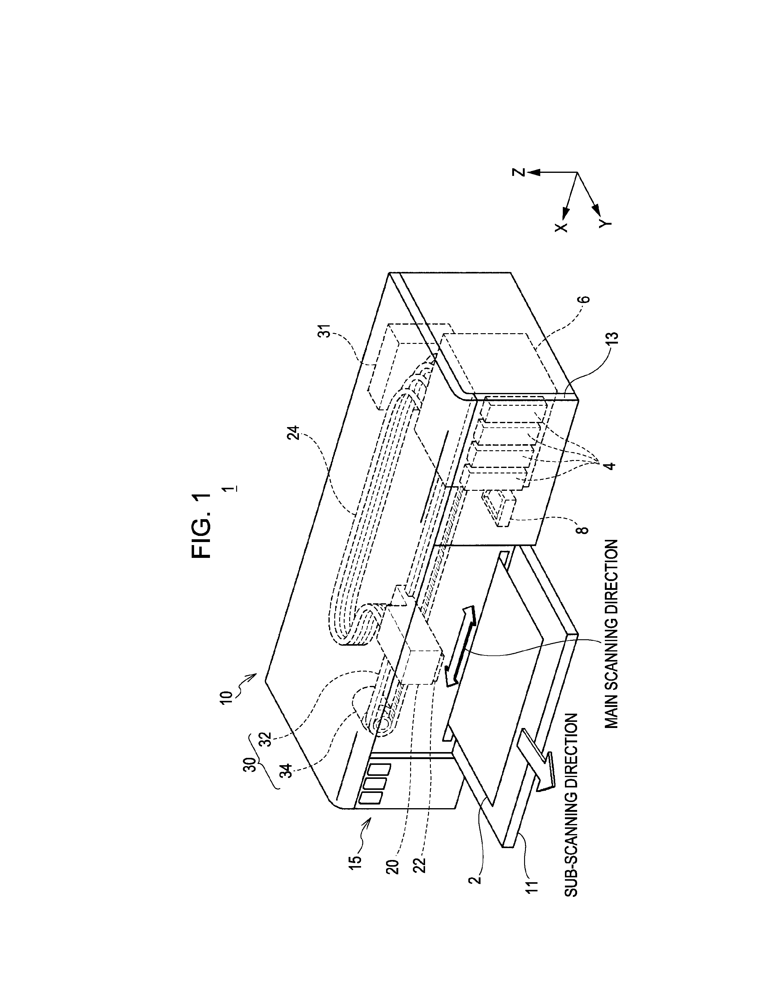
[0098]FIG. 1 is a perspective view illustrating the configuration of a printing material supply system 1. In FIG. 1, the X, Y, and Z axes which are three orthogonal spatial axes are drawn. The directions in which the arrows of the X axis, the Y axis, and the Z axis are directed respectively represent positive directions along the X axis, the Y axis, and the Z axis. The positive directions along the X axis, the Y axis, and the Z axis are respectively denoted by a +X axis direction, a +Y axis direction, and a +Z axis direction. The directions reverse to the directions in which the arrows of the X axis, the Y axis, and the Z axis are directed respectively represent negative directions along the X axis, the Y axis, and the Z axis. The negative directions along the X axis, the Y axis, and the Z axis are respectively denoted by a −X axis direction, a −Y axis direction, and a −Z axis direction. Directions along the...

first modified example

C-1. First Modified Example

[0201]In the above-described example, the cartridges 4 and 4a have the printing material accommodation portion 450. However, the case 9 may directly accommodate ink.

second modified example

C-2. Second Modified Example

[0202]In the above-described example, the positioning portion 756 is provided in the holder 750. However, the positioning portion 756 may be provided in the terminal block 724 by simplifying the configuration of the holder 750. In addition, in the above-described example, the apparatus side terminal group 721 that elastically deforms is employed. However, the apparatus side terminal group 721 that does not elastically deform may be employed. Even though the apparatus side terminal group 721 does not elastically deform, the apparatus side terminal group 721 moves slightly in the +Z axis direction after coming into contact with the cartridge side terminal group 521 when being inserted into the concave portion 90, and thus there is a possibility of the above-mentioned wiping effect being obtained.


PUM


Abstract

A cartridge includes a concave portion. The concave portion has an opening, first and second side walls, and a bottom wall, and the bottom wall has a tilted surface tilted. The tilted surface is provided with a cartridge side terminal group. The first side wall is provided with a first restriction portion which restricts movements in a +Z axis direction and a +X axis direction of an apparatus side terminal unit, and the second side wall is provided with a second restriction portion which restricts movements in the +Z axis direction and a −X axis direction of an apparatus side terminal unit.

Description

[0001]Priority is claimed under 35 U.S.C. §119 to Japanese Application No. 2012-022819 filed on Feb. 6, 2012, No. 2012-005347 filed on Jan. 13, 2012, and No. 2012-013238 filed on Jan. 25, 2012 which are hereby incorporated by reference in its entirety.BACKGROUND[0002]1. Technical Field[0003]The present invention relates to a cartridge which accommodates a printing material therein, a printing material supply system which includes a cartridge and a printing apparatus, and printing apparatus to which the cartridge is detachably mounted.[0004]2. Related Art[0005]A printer which is an example of a printing apparatus has a cartridge that accommodates ink therein and is detachably mounted thereto, and performs printing by supplying the ink from the cartridge to a printing head. Recently, a cartridge in which a circuit board that stores information regarding ink (for example, the color of ink) is mounted is used (for example, JP-A-2003-341100, JP-A-2007-230249, Specification of U.S. Pat. N...

Claims


Application Information

Patent Timeline
Patent Type & Authority Applications(United States)
IPC IPC(8): B41J2/175
CPCB41J2/175B41J2/17509B41J2/17526B41J2/1752B41J2/17553B41J2/17546B41J2/17506
Inventor AOKI, YUJISATOH, HIROSHI
Owner SEIKO EPSON CORP
Why Eureka
Try Eureka