Article for cleaving and polishing optical fiber ends

a technology of optical fiber and end parts, applied in the direction of optics, instruments, optical light guides, etc., can solve the problems of limiting the field-termination capability, limiting the use of optical fiber systems, and affecting so as to facilitate the insertion of one or more optical fibers, accurate alignment, orientation and facial conta

Inactive Publication Date: 2005-12-06
3M INNOVATIVE PROPERTIES CO
View PDF29 Cites 16 Cited by
  • Summary
  • Abstract
  • Description
  • Claims
  • Application Information

AI Technical Summary

Benefits of technology

[0012]Field installation of optical fiber connector plugs, in conjunction with the previously discussed field installable receptacles, offers several benefits including convenience, development of custom network segments, and the opportunity to order bulk supplies, rather than an array of standard components. These benefits could contribute to a reduction of optical fiber cable network installation costs.
[0013]The use of connector plugs and processes according to the present invention with previously available field installable sockets is convenient because it moves optical fiber termination from the controlled assembly environment of the factory to the field location where actual installation requirements are more clearly seen. Given the opportunity to construct cable systems to match the needs of a particular installation, an assembler is no longer limited to using factory terminated, standard cable lengths but has the advantage of custom building interconnecting cables. Custom interconnecting cables may be prepared using bulk optical fiber cable and connector components that may prove to be a less expensive option than reliance on supplier-determined, standard lengths of plug terminated cables. Field termination of connector plugs allows cable installers to return to more conventional methods of network installation.
[0019]Field assembly of a connector plug involves the relatively simple process of inserting one or more optical fibers into one side of crimp elements. The crimp elements have limited movement in elongate depressions formed in the floor of the molded base of any one of several embodiments of connector plugs according to the present invention. Connector plugs may be used with single optical fibers, but preferably the plug has a design to accommodate two or more optical fibers. Most preferably the plug may be used as a duplex plug, for two optical fibers contained in a single-jacketed cable. Each optical fiber enters its assigned crimp element to the point at which it contacts the cleaved and polished face of an optical fiber stub that was factory installed at the opposite end of the crimp element. A crimp element has a size and internal design to provide accurate alignment, orientation and facial contact between each newly cleaved optical fiber end and each optical fiber stub. Interfacial contact for optimum signal transmission through multi-fiber connector plugs relies upon the equal length of the optical fiber terminal portions, having slightly angled, cleaved and polished end faces, and the precise positioning of the crimp elements within the connector plug. After achieving the desired positioning and alignment, the newly cleaved fiber ends may be secured in the crimp elements using a crimping tool, also referred to herein as a compression cap.
[0020]Optical signal transmission relies upon accurate alignment full surface contact of the slightly angled ends of optical fibers and optical fiber stubs spliced together using crimp elements as described previously. Other features of connector plugs according to the present invention facilitate insertion of one or more optical fibers into the body of a connector plug and allow component size reduction, which results in optical fiber cable installations requiring less space or containing increased numbers of plug and socket connections.

Problems solved by technology

Until recently, cost was a deterrent to the use of optical fiber systems.
The lack of a corresponding method for field installation of connector plugs limits field-termination capability to optical fiber cables having a connector receptacle at each end.
This limitation restricts optical fiber cable interconnection to a single option in which field-terminated cables, having connector receptacles at both ends, alternate with factory terminated cables, having connector plugs on both ends.
Factory production of connector plug terminated optical fiber cables typically provides a limited variety of standard cable lengths.
Pre-terminated, factory assembled, optical fiber cables add expense and require more cable duct space than conventional cable systems.
Reliance on standard lengths of terminated cables also denies the advantage of efficient use of space associated with custom installations.

Method used


Image

  • Article for cleaving and polishing optical fiber ends
  • Article for cleaving and polishing optical fiber ends
  • Article for cleaving and polishing optical fiber ends

Examples


second embodiment

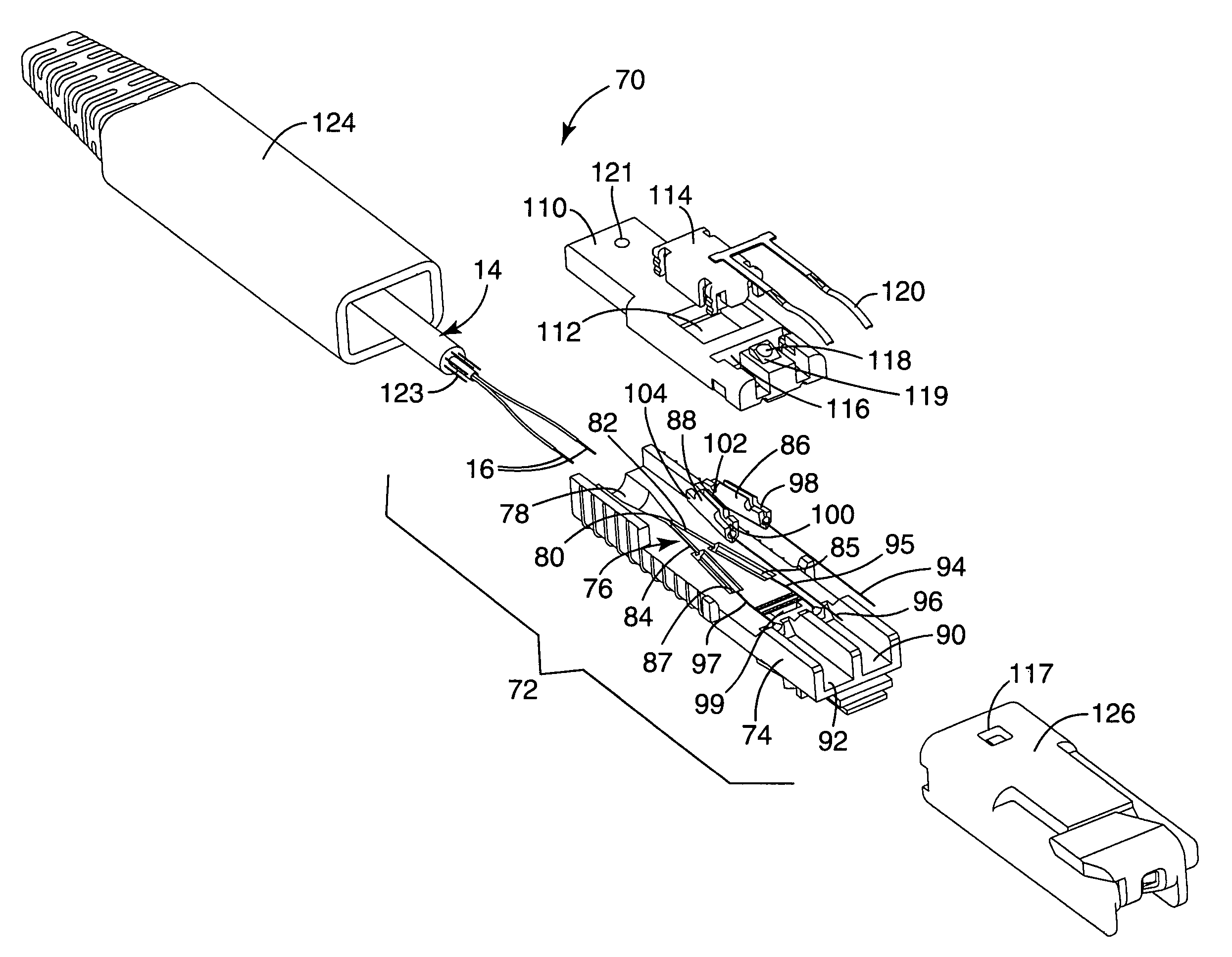
[0061]FIG. 9 provides an exploded perspective view of an optical fiber connector plug 270 according to the present invention including a molded connecting portion 272 that includes additional features to further increase the probability of optimal field assembly of a connector plug 270 according to the present invention. A connecting portion 272 comprises a fiber containment body 274 including a structured floor 276. The structured floor 276 has essentially the same features as the previously described structured floor 76 including a rear entry 78, extending to a junction 80 of a first fiber groove 82 and a second fiber groove 84 and first 86 and second 88 crimp elements. In addition to these features, the fiber containment body 274 further includes a tapered wall 277, molded into the floor 276 between the first fiber groove 82 and the second fiber groove 84, to prevent crossover of optical fibers 16, thereby directing them towards the correct crimp elements 86, 88 for maintaining o...

third embodiment

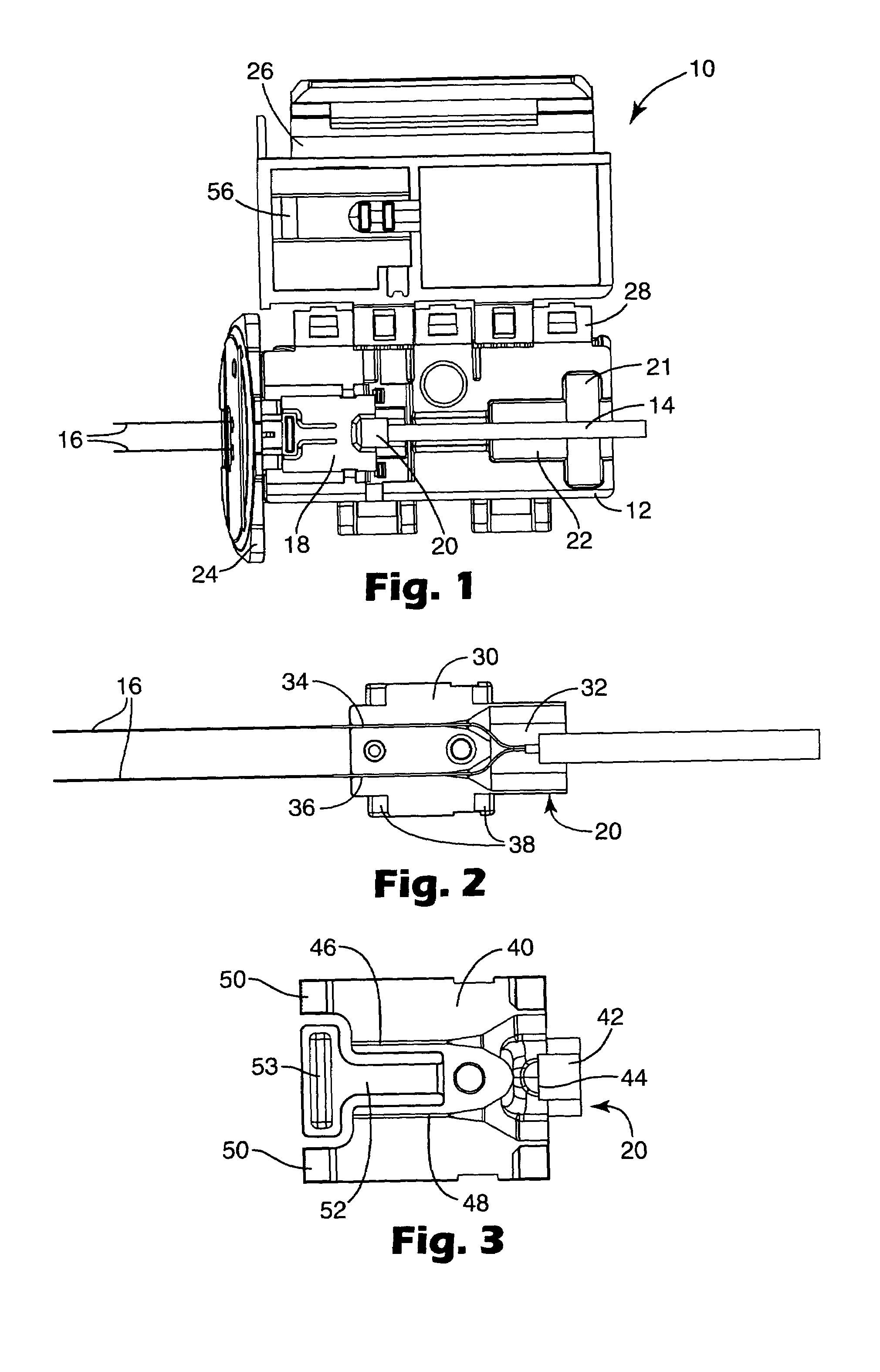
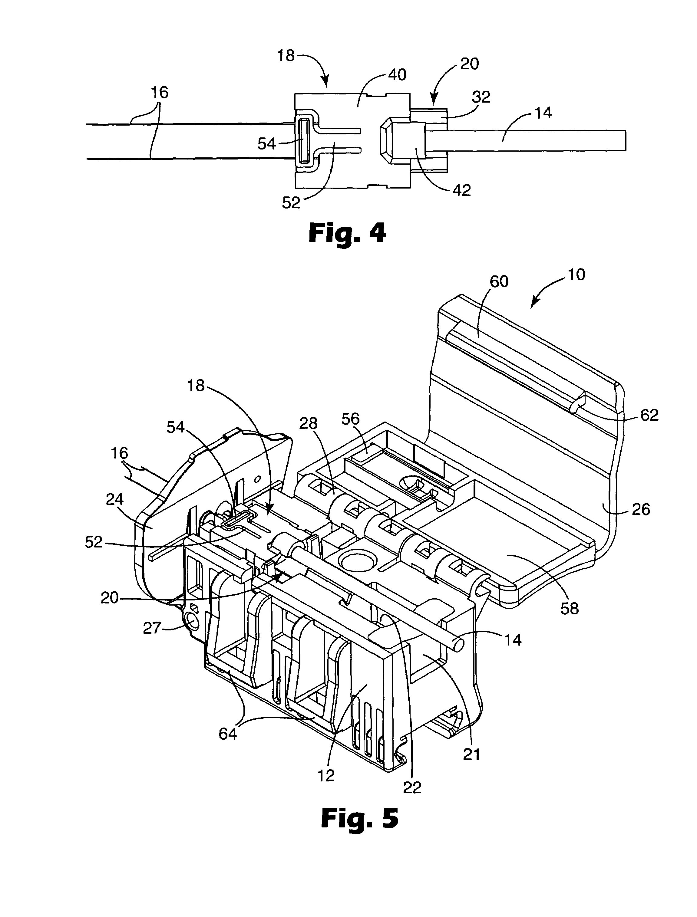
[0069]FIG. 14 provides an exploded perspective view of an optical fiber connector plug 370 suitable for field installation in situations where termination of an optical fiber cable 14 does not require installer dexterity associated with feeding stripped terminal portions of optical fibers 16 into channels 82, 84 or a slot 278 formed in pre-assembled connecting portions 72, 272 described previously. Instead, an installer has the option of field terminating one or more optical fibers 16 by applying a permanent fiber positioner 380 that may be used with a polishing puck 10 in place of the demountable, temporary optical fiber holder 18 described above. A permanent fiber positioner 380 includes a base-plate 330 connected to a cover-plate 340 in such a way that the positioner 380 is difficult to re-open after preparing the cable 14, to remove sheath and buffer layers and inserting the terminal portions of optical fibers 16 through channels in the positioner 380 and openings in the puck gu...


PUM


Abstract

An article for temporarily retaining an optical fiber cable including a stripped terminal portion of at least one optical fiber requiring cleaving followed by polishing of an end face thereof. The article comprises a housing having a recess for a demountable optical fiber holder. A demountable optical fiber holder includes a base-plate having at least a first fiber channel to receive at least one optical fiber. The base plate has a number of pockets. A cover plate for the demountable optical fiber holder includes a spring clamp, at least a first upper channel and a number of posts to mate with the pockets of the base-plate to assemble the holder. The article further includes a guide plate attached to the housing to pivot between a first pivot position and a second pivot position. A rotatable lid attached to the housing rotates between an open position and a closed position. The article temporarily retains the optical fiber cable for cleaving and polishing the end face thereof when the lid is closed.

Description

CROSS REFERENCE TO RELATED APPLICATION[0001]This application is a divisional of U.S. application Ser. No. 10 / 247,381, filed Sep. 19, 2002, now U.S. Pat. No. 6,816,662 B2, the disclosure of which is incorporated herein by reference.BACKGROUND OF THE INVENTION[0002]1. Field of the Invention[0003]The invention relates to devices for preparing and terminating optical fibers for interconnection in telecommunications networks using plug and socket assemblies that align the optical fibers for optimal signal transmission without the use of ferrules. More particularly, the present invention facilitates field processing of one or more cleaved and polished bare fiber ends using an apparatus for temporary containment during suitable preparation of terminal portions of optical fiber cables for field installation into the plug portion of an optical fiber plug and receptacle connector.[0004]2. Description of the Related Art[0005]The use of optical fibers in telecommunications networks offers the a...

Claims


Application Information

Patent Timeline
Patent Type & Authority Patents(United States)
IPC IPC(8): G02B6/25G02B6/38
CPCG02B6/25G02B6/3806G02B6/3846G02B6/3849G02B6/3863G02B6/3887G02B6/38875G02B6/3861
Inventor DOSS, DONALD G.HARDCASTLE, DAVID S.
Owner 3M INNOVATIVE PROPERTIES CO
Why Eureka
Try Eureka