Self correcting portable digital radiography detector, methods and systems for same

Active Publication Date: 2013-07-18
CARESTREAM HEALTH INC
View PDF18 Cites 50 Cited by
  • Summary
  • Abstract
  • Description
  • Claims
  • Application Information

AI Technical Summary

Benefits of technology

[0014]It is another aspect of this application to provide a radiographic imaging apparatus and/or methods that can provide a calibration mode operating to perform field calibration updates without operator intervention.
[0015]It is ano

Problems solved by technology

Inevitably, some number of pixels is found to be defective.
Because of normal and rough handling of portable radiographic detectors, the required intervals between calibration procedures, needed for maintaining suitable image quality, are less predictable for fully portable detectors.
However, this type of arbitrary interval negatively impacts productivity.
Most calibration procedures require x-ray exposures and therefore radiology staff time and attention and each calibration reduces the overall utilization time of the DR detector.
Clearly, there is a need to monitor the calibration state of the detector during regular clinical operation and to alert the user when calibration is needed, but calibration effectively disrupts operator workflow and increases access time for obt

Method used


Image

  • Self correcting portable digital radiography detector, methods and systems for same
  • Self correcting portable digital radiography detector, methods and systems for same
  • Self correcting portable digital radiography detector, methods and systems for same

Examples


Embodiment Construction

[0035]The following is a description of exemplary embodiments, reference being made to the drawings in which the same reference numerals identify the same elements of structure in each of the several figures, and similar descriptions concerning components and arrangement or interaction of components already described are omitted. Where they are used, the terms “first”, “second”, and so on, do not necessarily denote any ordinal or priority relation, but may simply be used to more clearly distinguish one element from another.

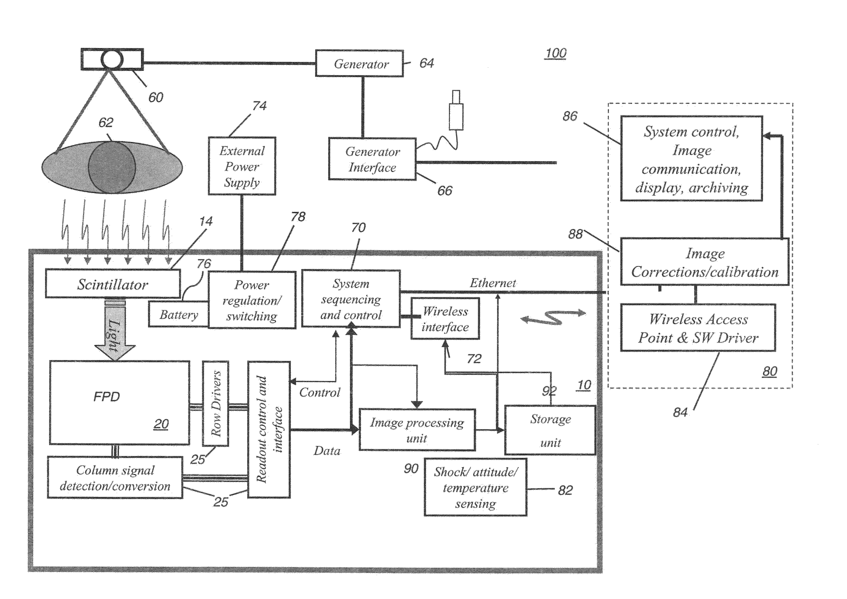
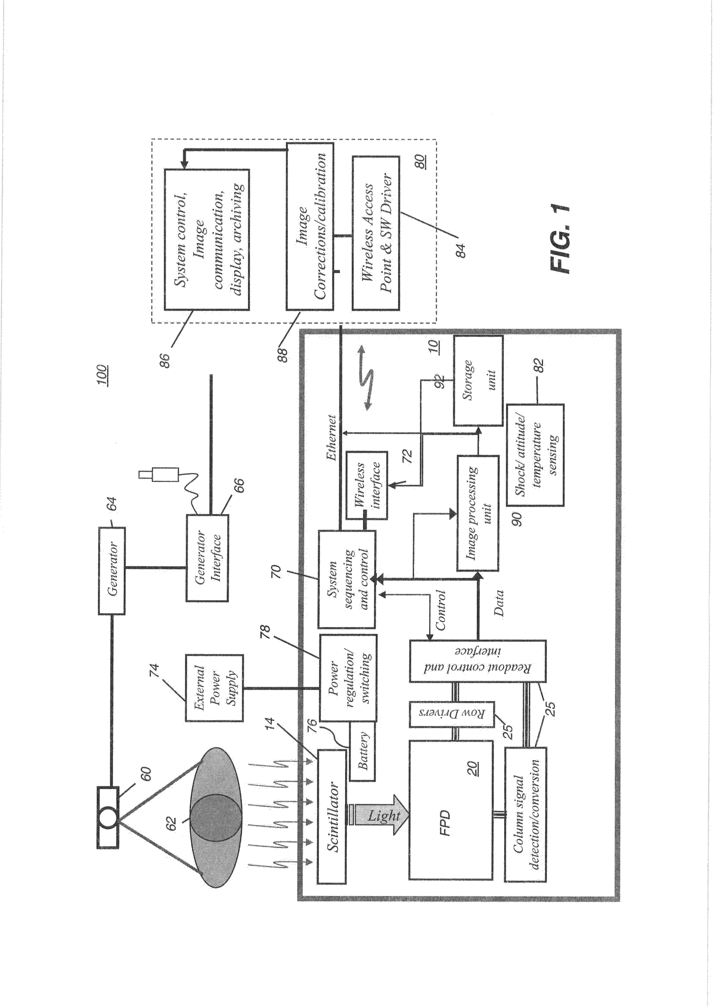
[0036]An embodiment of a digital radiographic (DR) imaging system and particular features for a portable DR detector are described with reference to FIG. 1. The schematic diagram of FIG. 1 shows, at a high level, an architecture of a radiographic imaging system 100 that can use a portable DR detector 10. An x-ray source 60, with a supporting generator 64 and a generator interface 66 directs radiation toward a patient or other object 62 and toward DR detector 10. C...


PUM


Abstract

Embodiments of radiographic imaging systems and/or methods can monitor the state of calibration of a digital x-ray detector, the detector including a solid state sensor with a plurality of pixels, an optional scintillating screen and at least one embedded microprocessor. In one embodiment, a method can use a computer or the embedded microprocessor or both, for setting a calibration operating mode of the portable detector; taking a plurality of dark images in the calibration mode; determining a dark difference image between pixel readings between two of the plurality of dark images; identifying pixels in the dark difference image that differ by over a threshold amount from at least some surrounding pixels in the dark difference image as defective pixels.

Description

FIELD OF THE INVENTION[0001]This invention generally relates to digital radiography (DR) imaging and more particularly relates to DR detector calibration and / or recalibration.BACKGROUND OF THE INVENTION[0002]Digital Radiography (DR) detectors directly transform received exposure energy to digital image data. These detectors commonly contain an array of light sensitive picture elements, or pixels, arranged in a matrix of rows and columns and a scintillator, consisting of a material, such as gadolinium oxysulfide, Gd2O2S:Tb (GOS) or cesium iodide (CsI), that absorbs x-rays incident thereon and converts the x-ray energy to visible light photons. In some configurations, the scintillator is in direct contact with the light sensitive array. The array of light sensitive elements can be any type of solid state sensor, such as a flat panel detector, a charge-coupled device, or CMOS detector. The light sensitive material converts the incident light into electrical charge which is stored in th...

Claims


Application Information

Patent Timeline
IPC IPC(8): G06K9/00G06V10/28G06V10/30
CPCG06K9/38G06K9/40H04N5/32G06T2207/30004H04N5/367G06T5/005G06T2207/10124H04N5/361G06T2207/10116G06V10/28G06V10/30H04N25/68H04N25/63
Inventor TOPFER, KARINCHANG, JEFF HSINHEILER, GREGORY N.
Owner CARESTREAM HEALTH INC
Why Eureka
Try Eureka