Solar collector

a solar collector and collector body technology, applied in the field of solar collectors, can solve the problems of premature stress cracking, water leakage at the weld, inadequate retention and sealing of the manifold,

Inactive Publication Date: 2013-07-25
BOSS RUBBER TECH
View PDF10 Cites 9 Cited by
  • Summary
  • Abstract
  • Description
  • Claims
  • Application Information

AI Technical Summary

Problems solved by technology

There are a number of drawbacks with rigid tubes, including possessing little elasticity and unsatisfactory sealing properties, resulting in inadequate retention and sealing when installed onto a manifold barb.
Generally the rigid tubes require special compression fittings to fix and seal the tube onto the barb, or alternatively, the manifold is over-moulded or welded onto the tubes in order to create a welded join at the interface to fix and seal the tube to the manifold, which can cause cracking and water leaks at the weld.
The drawbacks with flexible, plasticised or soft types of solar collectors are that the soft material cannot withstand the regular cycle of high pressure from the fluid therein followed by high vacuum pressure when the tube is drained of the fluid therein, and thus premature stress cracking can occur.
Also, the material can deform easily, thus making installation and retention on the manifold difficult.
Furthermore, the tubes can experience UV and chemical degradation over time, and can easily be damaged by pests or trampling by people during installation or maintenance.
Overall, these drawbacks result in a solar water heater that can be inefficient, costly and laborious to install and maintain, and susceptible to degradation and damage.

Method used


Image

  • Solar collector
  • Solar collector
  • Solar collector

Examples


first embodiment

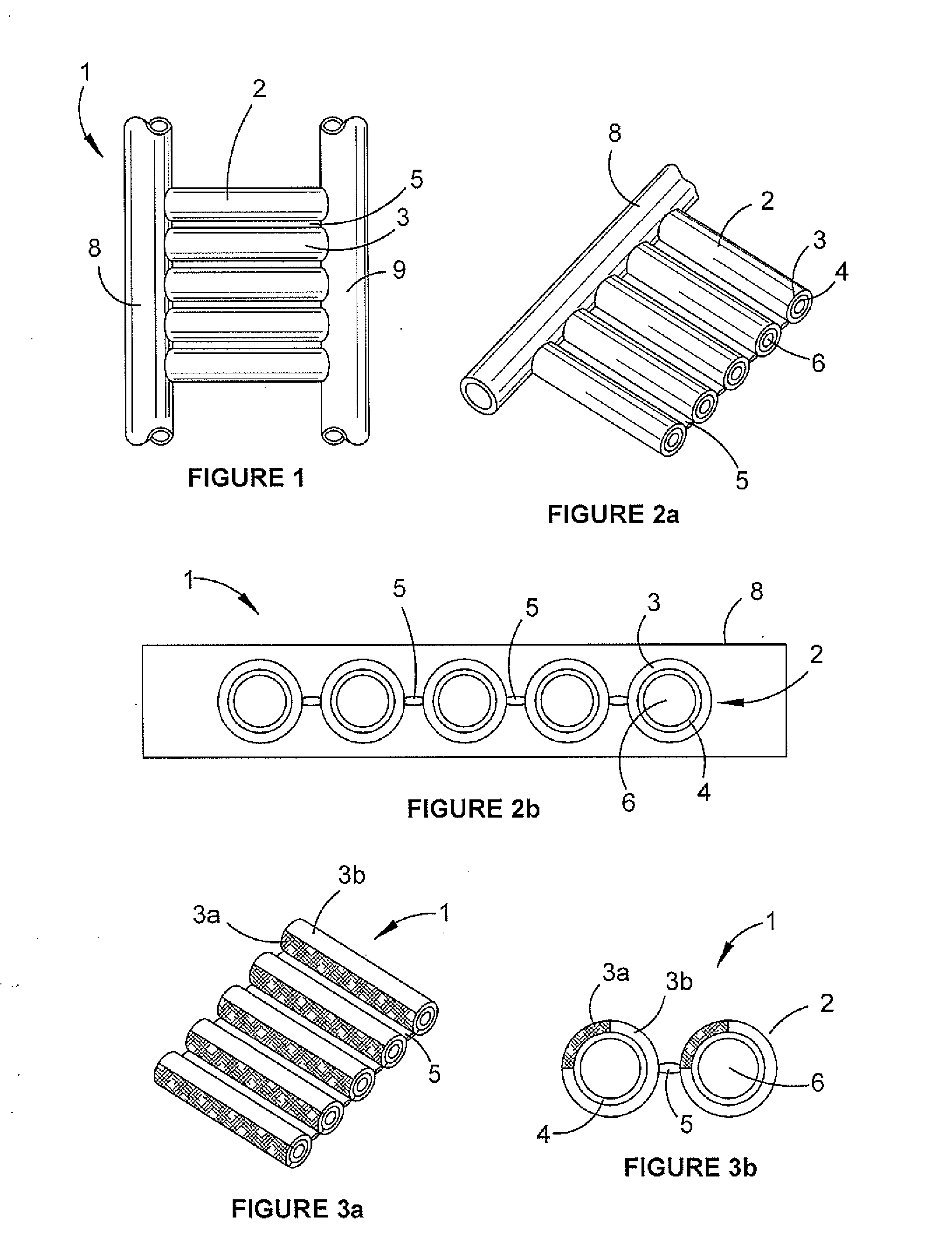
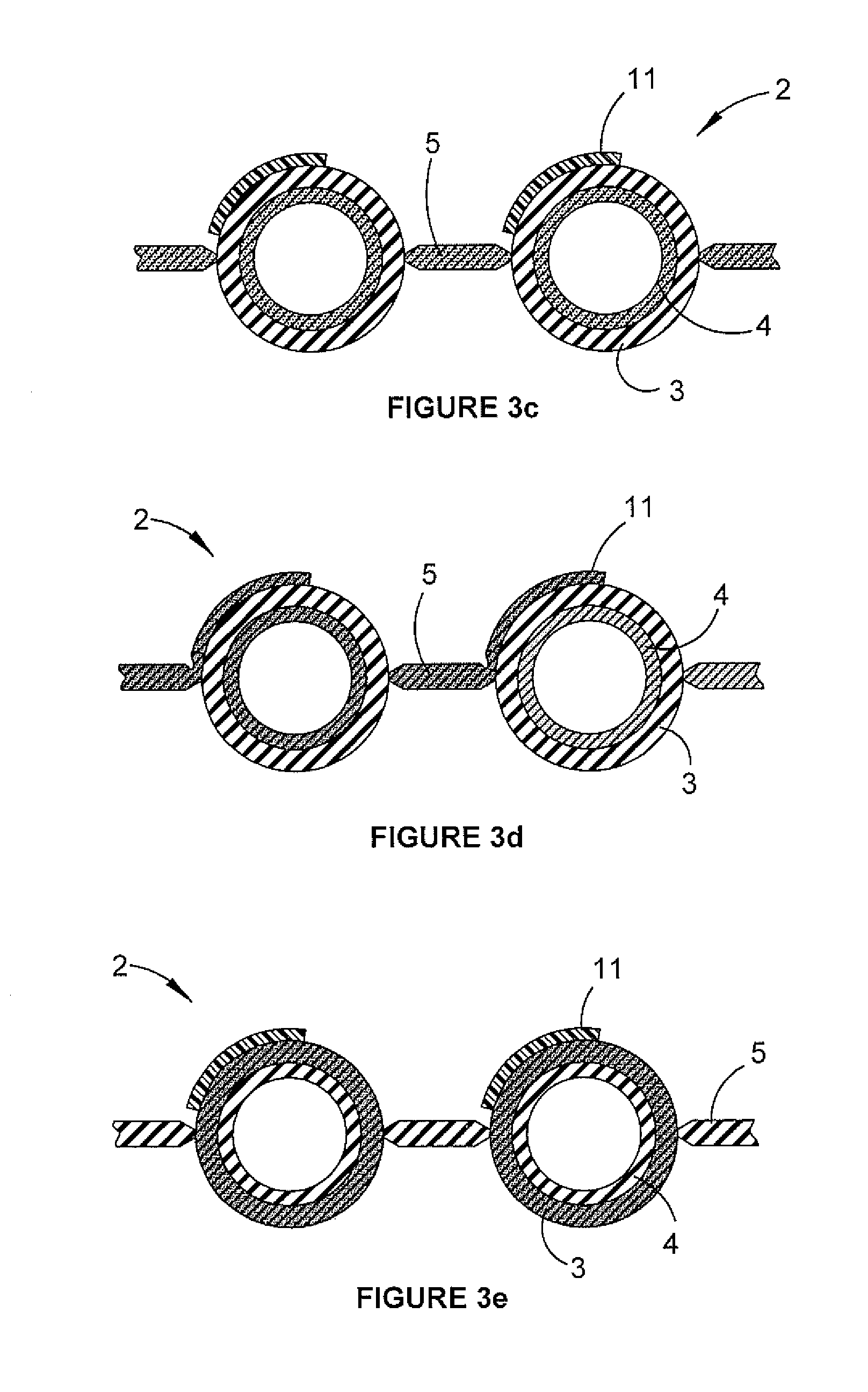
[0049]In a solar collector tube described herein the outer tube layer 3 is made of a harder polymer than the inner layer 4. This combination allows the solar collector polymer tube to absorb and transfer solar radiation to fluid inside the tubes with superior performance to that of known solar collectors while also ensuring product longevity.

[0050]The hardness of the outer layer 3 means it is able to withstand damage to the tube's integrity as a result of weight or sharp impact by various means such as humans, animals, or weather conditions, like storms, hail or projectiles.

[0051]With the material of the inner tube layer 4 being softer than the outer tube layer, it is more easily deformable and offers more friction so to be able to grip onto a manifold barb (not shown) used in connecting the polymer tubes to the inlet and outlet manifolds. The material of the inner tube layer 4 allows the polymer tube 2 to deform and securely grip the barbs of a manifold while still providing good s...

second embodiment

[0052]In a solar collector polymer tube described herein, the tube comprises at least two concentric and co-extruded tube layers where the inner tube is made of a cross-linked polymer and the outer layer is weldable. This version allows for each tube to be connected to a manifold by welding (typically in the factory) rather than by assembly onto a barb. The outer tube layer is fusable so that it can be welded to the manifold material by way of heat or sonic welding, over-moulding or other known polymer fusion techniques.

[0053]In the embodiment shown in FIG. 2b, the polymer tubes 2 are connected laterally via a web 5. Fluid, typically water, flows through a central bore 6 (see FIGS. 2a and 2b) in each co-extruded tube 2 and circulates within a closed or open solar collecting system to distribute heated fluid. In this embodiment, the web 5 connecting the tubes is a continuous hard, rigid web the same length as the tubes. The width of the web can be smaller, equal to or greater than th...


PUM

PropertyMeasurementUnit
diameteraaaaaaaaaa
distanceaaaaaaaaaa
widthaaaaaaaaaa

Abstract

A solar collector for heating and transferring fluids, having an inlet manifold and an outlet manifold through which fluid is respectively transferred into and out of the solar collector; and a plurality of polymer tubes each connected between the inlet and outlet manifolds, the polymer tubes having co-extruded concentric inner and outer tube layers, wherein the outer tube layer is composed of a harder polymer than the inner tube layer.

Description

[0001]The present invention relates to a solar collector for use in a solar water heater, more particularly in heating pools or spas or for use in water heating applications such as domestic hot water services and horticultural applications, for example, for heating plant root soil.BACKGROUND OF THE INVENTION[0002]Various types of solar water heaters have been known for many years. In one particular type commonly used for pool or spa water heating, water is moved from a source (such as a pool or spa) into a solar collector (also known as a strip collector or a solar absorber), whereby solar radiation from the sun is absorbed by the solar collector and heats the water contained therein. The heated water is then returned back to the source in a closed circuit arrangement.[0003]For domestic hot water applications the solar collector strip is generally contained within an enclosure beneath a clear panel such as tempered glass or plastic sheeting such a polycarbonate Corrlute sheeting. T...

Claims


Application Information

Patent Timeline
Patent Type & Authority Applications(United States)
IPC IPC(8): F24J2/24B29C48/09B29C48/11B29C48/21F24S10/70
CPCB29C47/0023B29C47/0028B29C47/065B29L2031/601F16L9/133F16L11/04F28F2255/16F24J2/265F24J2/4654F24J2/482F24J2/488Y02E10/44F24J2/245F24J2/243F24S70/275F24S70/14F24S10/753F24S80/10F24S2080/05B29C48/09B29C48/11B29C48/21F24S10/73F24S10/742
Inventor MILLS, NORMAN
Owner BOSS RUBBER TECH
Why Eureka
Try Eureka