Reusable beverage container with flexible spout

Inactive Publication Date: 2013-07-25
GABI CONCEPTS
View PDF15 Cites 20 Cited by
  • Summary
  • Abstract
  • Description
  • Claims
  • Application Information

AI Technical Summary

Benefits of technology

[0011]A general object of the invention is to provide a reusable beverage container with a flexible sp

Problems solved by technology

A problem with prior beverage containers is that the spouts are generally hard and rigid, and, therefore, not tactilely pleasing to a user while consuming the beverage.
Hard and rigid spouts and straws are simply not always comfortable in the mouth.
This poor fit can also cause leakage of the beverage about the circumference of the spout or straw during consumption.
Another problem with prior spouts and straws is that liquid can generally flow freely therethrough.
If liquid is allowed to flow freely, it can flow suddenly and unexpectedl

Method used


Image

  • Reusable beverage container with flexible spout
  • Reusable beverage container with flexible spout
  • Reusable beverage container with flexible spout

Examples


embodiment i (preferred embodiment)

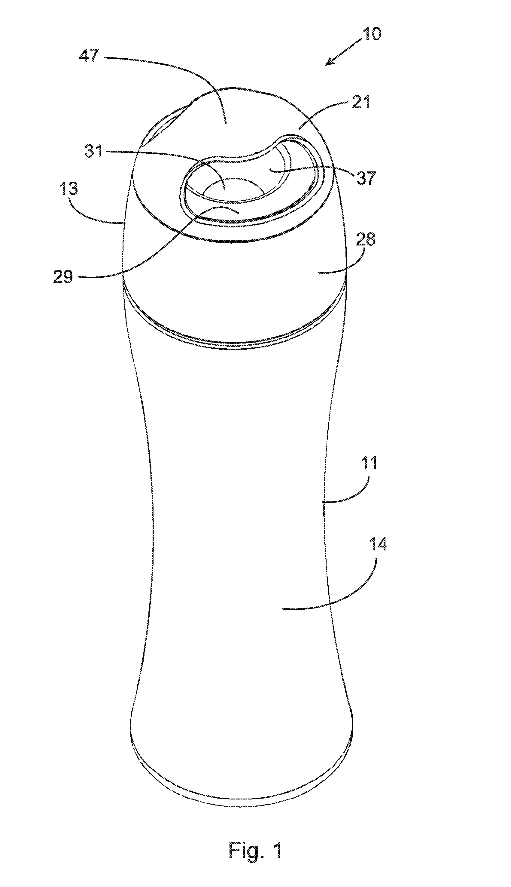
[0053]Adverting now to the drawings, FIG. 1 is a perspective view of a preferred embodiment of the invention. Beverage container 10 includes receptacle 11 and cap 13. Cap 13 includes convex handle 47, which extends across the diameter of second top portion 21 of cap 13, and is open on both sides.

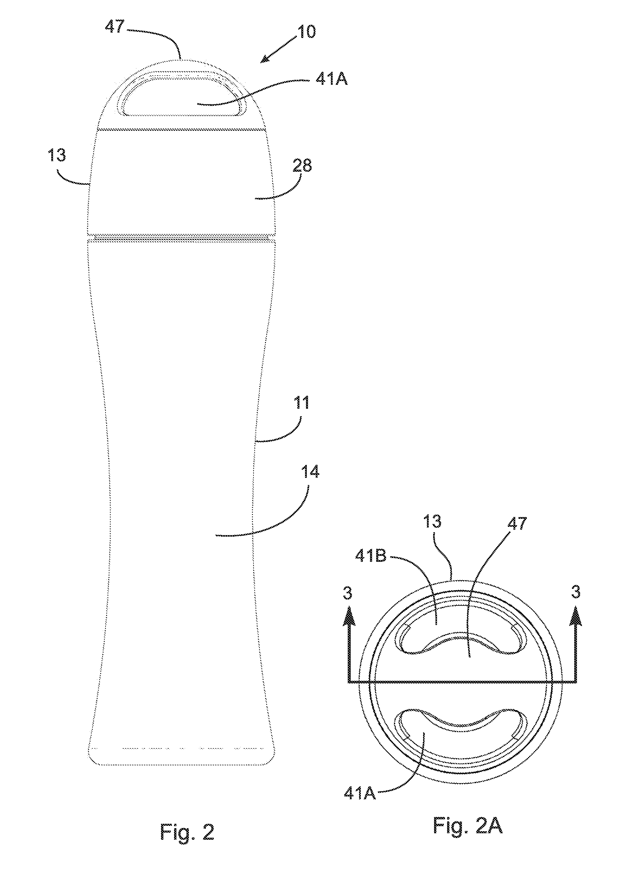
[0054]FIG. 2 is a front view of the beverage container shown in FIG. 1.

[0055]FIG. 2A is a top view of the beverage container shown in FIG. 2.

[0056]FIG. 9 is a cross-sectional view of a preferred embodiment of cap 13 of beverage container 10. As also depicted in FIG. 1, handle 47 extends across the diameter of second top portion 21 of cap 13, and is open on both sides. Aperture 41 enables user 90 (not shown in FIG. 9A) to hold beverage container 10 by gripping through aperture 41 and wrapping his or her hand around handle 47 for a secure grip. FIG. 9A is a top perspective view of cap 13 shown in FIG. 9. FIG. 9B is a bottom perspective view of cap 13 shown in FIG. 9.

embodiment i -

Embodiment I-A (Long Spout Embodiment)

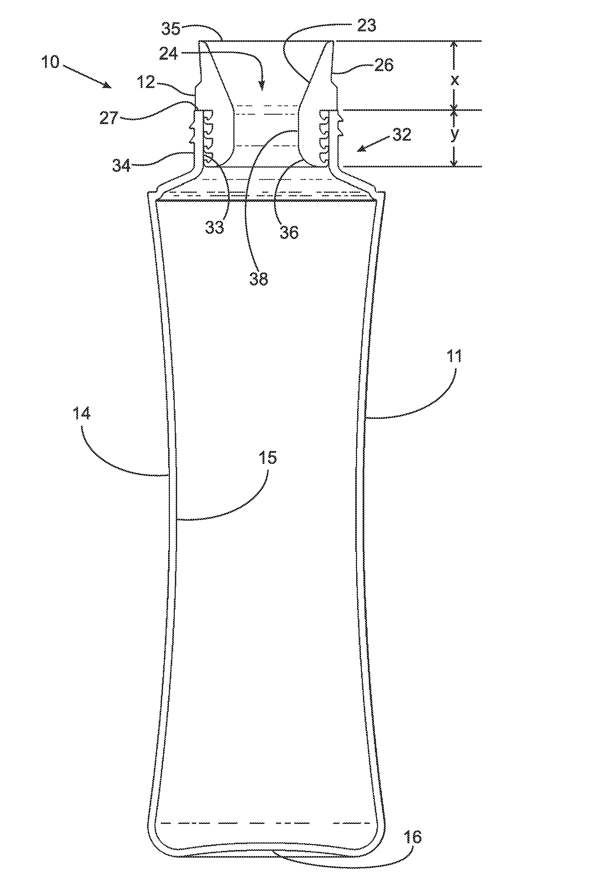
[0057]In the long spout embodiment, as shown in FIGS. 3A, 4, 4A, 5, 6, 7, 7A, 7B, and 11, the spout sealably engages the neck portion of the receptacle. When the spout is inserted into the neck portion, the spout extends upwardly beyond the rim of the neck portion. In a preferred embodiment, the spout extends upwardly approximately 1.905 centimeters above the rim of the neck portion. This dimension is not critical, and is not intended to limit the scope of the appended claims. Perhaps more importantly, in the long spout embodiment, is the ratio of the length of the spout relative to the length of the neck portion of the container. As shown in FIG. 3A, the length “x” of the portion of the spout that extends beyond the rim of the neck is approximately equal to the length “y” of the neck portion itself. In a preferred embodiment, in the long spout embodiment, the ratio y / x is approximately equal to 1, or in the general range of 0.8-1.2.

[0058]FIG. 3...

embodiment i-b (

Short Spout Embodiment)

[0066]In the short spout embodiment, as shown in FIGS. 3B, 6, 8, 8A, 8B, 10, 10A, and 12, the spout sealably engages the neck portion of the receptacle similar to the long spout embodiment. However, the spout only extends slightly above the rim of the neck portion. The rim of the neck portion extends upwardly into a channel in the spout to secure the spout to the neck portion.

[0067]FIG. 3B is a cross-sectional view of embodiment IB of beverage container 10 taken generally along line 3-3 of FIG. 1. We refer to this as the “short spout” embodiment of the invention. In this figure, cap 13 has been removed, such that flexible spout 12 is shown inserted into neck portion 32 of receptacle 11. In this embodiment, spout 12 extends slightly above rim 27 of neck portion 32. Spout 12 engages rim 27 via channel 48, such that rim 27 extends upwardly into channel 48 to secure spout 12 to neck portion 32. It should be appreciated that in a preferred embodiment, the spout is ...


PUM


Abstract

The invention is a reusable beverage container including a cap having a first top portion and an inner flange extending downwardly therefrom, a receptacle, a neck portion, and a flexible spout. The neck portion includes an inner diameter surface and an outer diameter surface. The spout has a through-bore therein, a first opening rim and a second opening rim formed by the through-bore, and an outer surface having a plurality of ribs annularly disposed about the outer surface. The spout includes a first portion. The neck portion is operatively arranged to receive the first portion of the spout. The second portion of the spout extends upwardly beyond the neck portion, and the plurality of ribs is sealably engaged against the inner diameter surface of the neck portion. The first opening rim is sealably engaged to the first top portion when the cap is secured to the neck portion.

Description

CROSS REFERENCE TO PRIOR APPLICATIONS[0001]This application is filed under 35 U.S.C.§120 and §365(c) as a continuation of International Patent Application No. PCT / CA2011 / 050076 filed Feb. 10, 2011, which application claims priority from U.S. Provisional Patent Application No. 61 / 348,150, filed on May 25, 2010, which applications are incorporated herein by reference in their entireties.FIELD OF THE INVENTION[0002]The present invention broadly relates to beverage containers, and, more particularly, to a reusable beverage container with a flexible spout.BACKGROUND OF THE INVENTION[0003]Beverage containers are well known. Generally, a beverage container includes a receptacle, a spout assembly, and, optionally, a cap.[0004]A problem with prior beverage containers is that the spouts are generally hard and rigid, and, therefore, not tactilely pleasing to a user while consuming the beverage. Hard and rigid spouts and straws are simply not always comfortable in the mouth. Rigid spouts and st...

Claims


Application Information

Patent Timeline
IPC IPC(8): B65D5/72
CPCB65D41/0407B65D47/06B65D47/122B65D2547/063B65D51/242Y02W30/80
Inventor MENCELES, ANDREWPOISSANT, PHILIP LAURIERMELANSON, MICHAELPOISSANT, NICHOLAS PAUL
Owner GABI CONCEPTS
Why Eureka
Try Eureka