

Electric power steering device
a technology of electric power steering and steering shaft, which is applied in the direction of control/drive circuits, magnetic circuit rotating parts, magnetic circuit shape/form/construction, etc., can solve the problems of complex assembly work of components, reduced components, and reduced components, so as to improve the radiation capability of the motor and improve the radiation capability of the stator
- Summary
- Abstract
- Description
- Claims
- Application Information
AI Technical Summary
Benefits of technology
Problems solved by technology
Method used
Image

Examples
embodiment 1
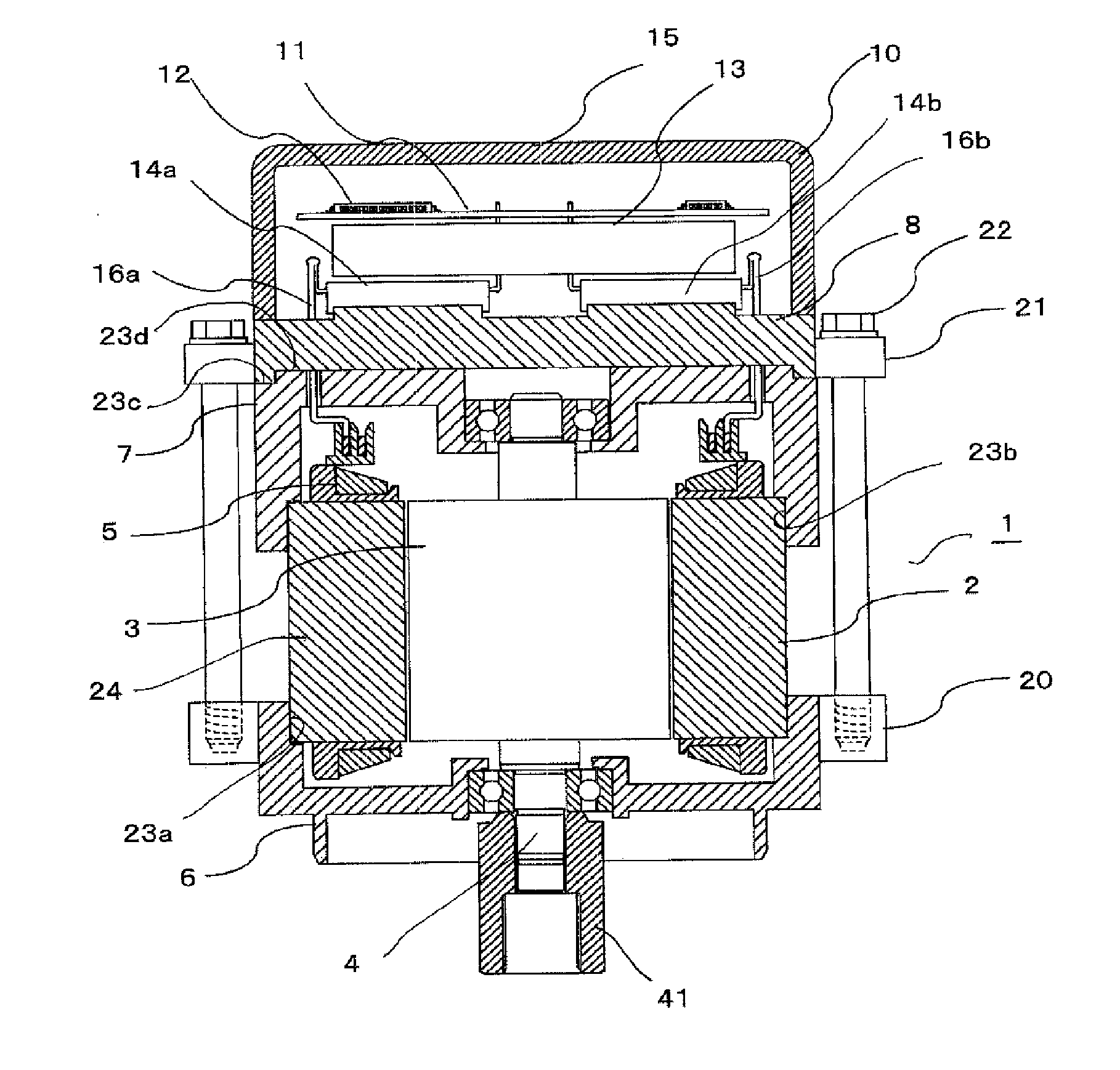
[0018]Hereinafter, an electric power steering device according to Embodiment 1 of the present invention will be explained in reference to the drawings. FIG. 1 is a cross-sectional diagram illustrating the electric power steering device according to Embodiment 1 of the present invention. In FIG. 1, a motor 1 includes a stator core 24 composed of a laminated iron core on which a plurality of iron plates are laminated, a stator 2 composed of a stator winding 5 attached to the stator core 24, a rotor 3 inserted to inner space in the stator 2, and an output shaft 4 fixed to the center portion of the rotor 3. A first side, from which a power output of the output shaft 4 is outputted, is called as a front side (lower side in FIG. 1), and a second side, which is a reverse side of the first side, is called as a rear side (upper side in FIG. 1). A front housing 6 as a first housing and a rear housing 7 as a second housing are respectively attached to a front side and a rear side of the stator...
embodiment 2
[0042]In an electric power steering device according to Embodiment 2 of the present invention, a control device is mounted at an output side, in other words, at a front side of the motor. FIG. 3 is a cross-sectional diagram illustrating the electric power steering device according to Embodiment 2 of the present invention, and reference symbols, which are the same as those in FIG. 1, refer to the same or equivalent parts. In the configuration of the electric power steering device, a heat sink 8, power modules 14a and 14b, a relay member 13, and a control board 11 are sequentially laminated and assembled in order of a long distance between each of these components and a motor 1. Therefore, each of kindred components can be used in an equivalent concept according to Embodiment 1, so that a design of the arrangement of the control device can be easily changed from a front side as described in Embodiment 1 to a rear side as described in Embodiment 2.
[0043]There are differences between a ...
embodiment 3
[0049]Hereinafter, an electric power steering device according to Embodiment 3 of the present invention will be explained in reference to the drawings. FIG. 4 is a cross-sectional diagram illustrating the electric power steering device according to Embodiment 3 of the present invention, and FIG. 5 is a plane view illustrating a rear housing detached from the electric power steering device according to Embodiment 3 of the present invention. Differences between the electric power steering device according to Embodiment 3 and the electric power steering device according to Embodiment 2 are positions of the edge portions and configurations of the stator cores. In addition, reference symbols, which are the same as those in FIG. 3, refer to the same or equivalent parts.
[0050]In FIG. 4 and FIG. 5, a stator 2, a rotor 3, a front housing 6, and a heat sink 8 are configured, in a similar way in Embodiment 2, toward a lower direction with respect to a rear housing 7. Flange portions 26 of the ...
PUM
 Abstract
Description
Claims
Application Information