
Apparatus and method for transmitting wireless power by using resonant coupling and system for the same

a technology of resonant coupling and antenna, which is applied in the direction of electric power, electric vehicles, transportation and packaging, etc., can solve the problems of reducing and affecting the efficiency of wireless power transmission

Active Publication Date: 2013-07-25
SAMSUNG ELECTRONICS CO LTD
View PDF13 Cites 62 Cited by
  • Summary
  • Abstract
  • Description
  • Claims
  • Application Information

AI Technical Summary

Benefits of technology

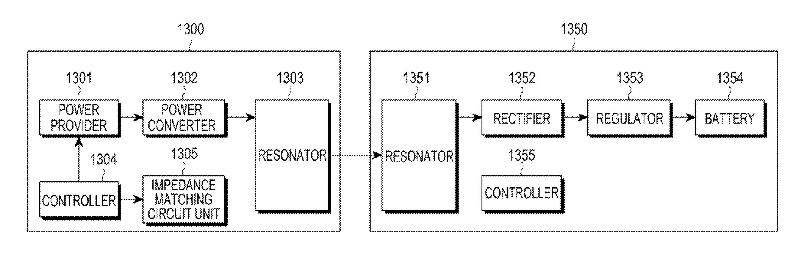
The present invention is about a new way to transmit wireless power using a resonant coupling. It includes a converter to convert DC power to AC power, a controller to adjust the Q factor of a resonator to match the frequency of the converted AC power, and control the adaptive impedance matching, and a resonator to wirelessly transmit the converted AC power to a receiver. This method and apparatus can improve the efficiency and reliability of wireless power transmission.

Problems solved by technology

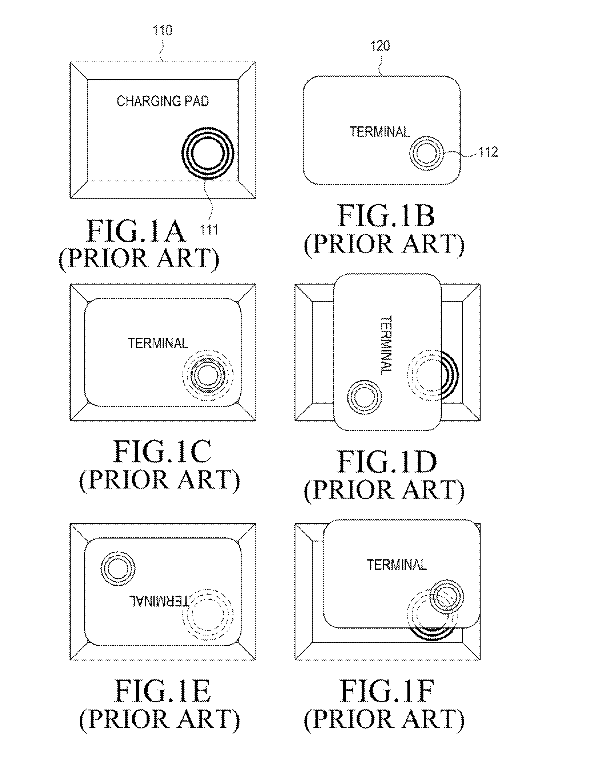
However, FIGS. 1D to 1F illustrate examples where coil arrangement states of the Tx coil of the transmitter and the Rx coil of the receiver are not good, which results in poor wireless power transmission.
The wireless power charging technology basically requires accurate arrangements of the Tx coil and the Rx coil and has a problem in that a size of the Tx coil and a size of the Rx coil should be almost the same.
The Rx coil is located in a main body of a tablet Personal Computer (PC), but internal components of the main body of the tablet PC may prevent the Rx coil from being located in the center thereof In this case, there is a limitation in the arrangements of the Tx coil and the Rx coil.
For example, when the tablet PC is placed on the wireless charging pad, if the tablet PC is placed with a rotation of 90 degrees or placed in such a manner that a part of a main body of the tablet PC is not in contact with the wireless charging pad, arrangement states of the Tx coil within the wireless charging pad and the Rx coil within the tablet PC are not good, thereby rapidly decreasing the efficiency and stopping the wireless power transmission.

Method used


Image

  • Apparatus and method for transmitting wireless power by using resonant coupling and system for the same
  • Apparatus and method for transmitting wireless power by using resonant coupling and system for the same
  • Apparatus and method for transmitting wireless power by using resonant coupling and system for the same

Examples


Embodiment Construction

[0033]Hereinafter, embodiments of the present invention will be described in detail with reference to the accompanying drawings. In the following description, the same elements will be designated by the same reference numerals although they are shown in different drawings. In the following description, a detailed description of known functions and configurations incorporated herein will be omitted for the sake of clarity and conciseness.

[0034]The terms described below are defined considering functions performed in the present invention and may vary depending on the user, intention of the user, or practice.

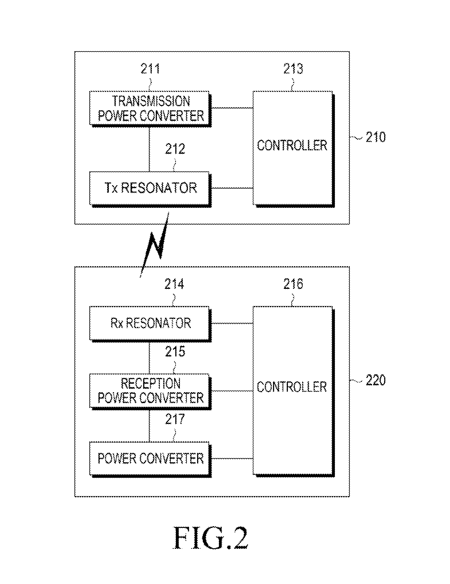
[0035]FIG. 2 illustrates a wireless power charging system using a resonant coupling according to an embodiment of the present invention. FIG. 2 includes a transmitter 210 for transmitting wireless power and a receiver 220 for receiving, and then charging, the wireless power.

[0036]The transmitter 210 includes a transmission power converter 211 for converting DC power to AC power, a...


PUM


Abstract

Disclosed are an apparatus and a method for charging power using a resonant coupling. The apparatus includes a transmission power converter for converting Direct Current (DC) power to Alternating Current (AC) power, a controller for adjusting a Q factor of a transmission resonator by using a frequency of the converted AC power and a resonant frequency of the transmission resonator and controlling adaptive impedance matching, and a transmission resonator for wirelessly transmitting the converted AC power to a receiver through the adjusted Q factor and the controlled adaptive impedance matching, the transmission resonator having a coil installed in the transmitter.

Description

PRIORITY[0001]This application claims priority under 35 U.S.C. §119(a) to Korean Application Serial No. 10-2012-0006544, which was filed in the Korean Intellectual Property Office on Jan. 20, 2012, and Korean Application Serial No. 10-2012-0046226, which was filed in the Korean Intellectual Property Office on May 2, 2012, the contents of both of which are incorporated herein by reference.BACKGROUND OF THE INVENTION[0002]1. Field of the Invention[0003]The present invention relates generally to an apparatus and a method for transmitting power, and more particularly, to an apparatus and a method for transmitting wireless power by using a resonant coupling.[0004]2. Description of the Related Art[0005]A wireless power charging technology is currently being used for numerous electronic devices, such as an electric toothbrush, an electric shaver, a mobile phone, and a digital camera. Extensive research is currently being conducted on wireless charging of a large size battery for an electri...

Claims


Application Information

Patent Timeline
Patent Type & Authority Applications(United States)
IPC IPC(8): H02J7/00
CPCH02J7/0042H02J7/025H02J7/0044H02J5/005H02J50/80H02J50/12H02J50/40
Inventor PARK, SUNG-KWEONKO, KIL-SOOKIM, KI-HYUNPARK, SE-HOPARK, JIN-HYOUNGLEE, SEA-YOUNGLEE, YOUNG-MINJUNG, HEE-WONKIM, HONG-KWEUNHAN, SEUNG-WOO
Owner SAMSUNG ELECTRONICS CO LTD
Learn More