
Direct type backlight device and liquid crystal display using the same

a backlight device and liquid crystal display technology, applied in the field of backlight devices, can solve the problems of chromaticity unevenness and brightness unevenness in the overall area light source need to be suppressed, the optical path length from the leds to the diffusion plate is short, and it is comparatively difficult to uniformly disperse the light from the respective color leds within the surface. the effect of color unevenness on the periphery of the display region and brightness unevenness on the periphery

Active Publication Date: 2013-07-25
NEC LCD TECH CORP
View PDF13 Cites 30 Cited by
  • Summary
  • Abstract
  • Description
  • Claims
  • Application Information

AI Technical Summary

Benefits of technology

The present invention provides a direct type LED backlight device that can improve color unevenness on the periphery of the display region without increasing the driver and control circuit and changing the contour of a liquid crystal panel or an LCD device. This can be achieved by improving the position of the LEDs in relation to the display region. The device can also improve brightness unevenness on the periphery of the display region without increasing the driver and control circuit and changing the contour of a liquid crystal panel or an LCD device. The invention allows for better uniformity of color and brightness across the display region, improving the overall quality of the display.

Problems solved by technology

Furthermore, brightness unevenness and chromaticity unevenness in the overall area light source need to be suppressed within predetermined ranges.
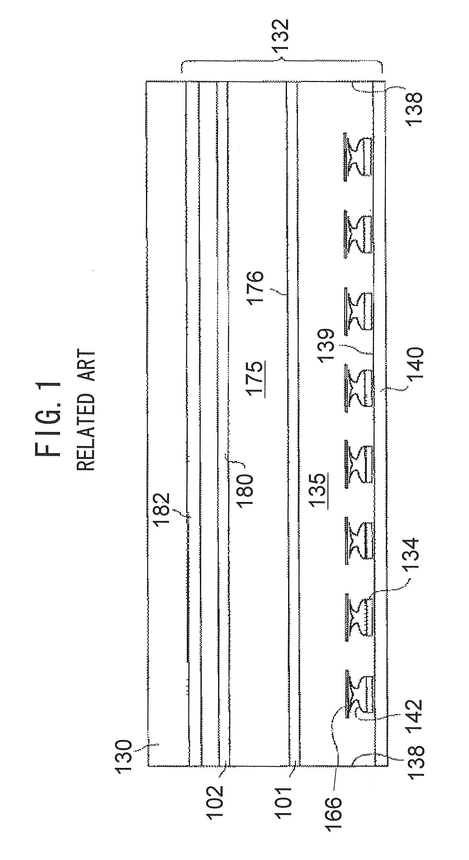
However, when the thickness of the direct type backlight device is limited, in other words, when the direct type backlight device has a thin profile, the optical path length from the LEDs to the diffusion plate is short and therefore, it is comparatively difficult to disperse uniformly the light from the respective color LEDs within the surface.
As a result, there arises a difficulty that brightness unevenness and chromaticity unevenness are likely to occur.
Accordingly, in-plane color unevenness is likely to occur.
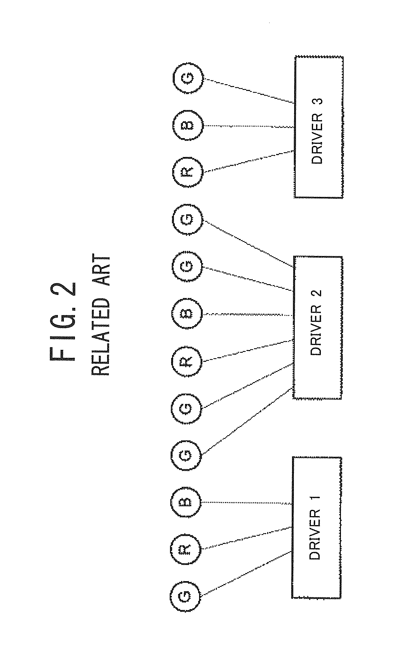
However, driving the LEDs 134 located in the end parts of the LED strip and the LEDs 134 located in the middle part thereof by different drivers similar to the aforementioned conventional backlight device 132 will induce problems, such as increase in costs due to increase of the drivers and their control circuits, and occupation space increase (this leads to contour change of the LCD).

Method used


Image

  • Direct type backlight device and liquid crystal display using the same
  • Direct type backlight device and liquid crystal display using the same
  • Direct type backlight device and liquid crystal display using the same

Examples


first embodiment

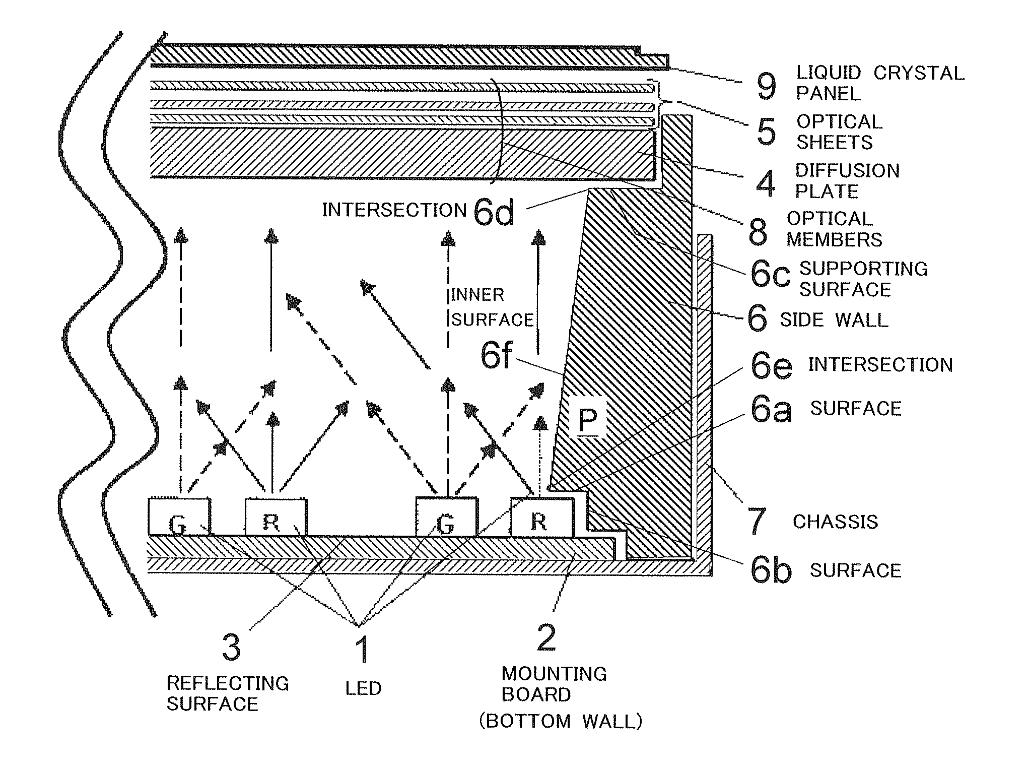
[0075]A direct type LED backlight device according to a first embodiment of the present invention is shown in FIGS. 3 and 4.

[0076]As shown in FIG. 3, the direct type LED backlight device according to the first embodiment of the present invention comprises a LED array formed by a plurality of LEDs 1, a mounting board 2, a set of optical members 8, a side wall 6, and a chassis 7.

[0077]The LED array is constituted by combining a plurality of LEDs 1 each emitting red (R), green (G) or blue (B) light and disposing the LEDs 1 on the inner surface of the mounting board 2 to have a predetermined layout. The LED array mixes the red, green, and blue light to generate white light. Here, each of the LEDs 1 is of the “top-view” type that which emits red, green, or blue light perpendicular to the package thereof.

[0078]The concrete structure of the LED array used in the first embodiment is shown in FIG. 4. As shown in FIG. 4, four LEDs 1 that emit respectively red, green, green, and blue light are...

second embodiment

[0118]FIG. 8 is a partial plan view showing the structure of the LED array used in a direct type LED backlight device according to a second embodiment of the present invention, where the LED array is seen from their emission surface side (i.e., the side of the optical sheets 8).

[0119]With the second embodiment, as shown in FIG. 8, the LED clusters 1A have a staggered layout or pattern. The second embodiment is different from the aforementioned first embodiment at this point. The other structure of the second embodiment is the same as the first embodiment.

[0120]Since the LED cluster 1A has a staggered layout, the distance between the adjoining clusters 1A can be made constant. In addition, since the distance between the clusters 1A is constant, the respective color light from the respective LEDs 1 is well mixed with each other to have a good balance within the overall backlight device according to the second embodiment. Accordingly, with the backlight device according to the second e...

third embodiment

[0121]FIG. 9 is a cross-sectional view showing the structure of the main part of a direct type LED backlight device according to a third embodiment of the present invention.

[0122]As shown in FIG. 9, in the third embodiment, although the structure itself of the backlight device is the same as that of the aforementioned first embodiment, the optical characteristic of the surfaces 6a and 6b of the side wall 6, which are located on the side of the mounting board 2, is different. Specifically, in the first embodiment, the surface 6a which is parallel to the reflecting surface 3 of the side wall 6, and the surface 6b which is continuous to the surface 6a and perpendicular to the reflecting surface 3 have a non-reflective characteristic (i.e., an optical absorption characteristic). On the contrary, in the third embodiment, the surface 6a has a reflection characteristic and the surface 6b has an optical absorption characteristic. The other structure is the same as the above-described first ...


PUM

PropertyMeasurementUnit
center-to-center distanceaaaaaaaaaa
sizeaaaaaaaaaa
distanceaaaaaaaaaa

Abstract

A direct type LED backlight device improves color unevenness on the periphery of the display region without increase of the driver and its control circuit and contour change of a liquid crystal panel. This device includes a bottom wall, a set of optical members arranged opposite to an inner surface of the bottom wall, a side wall maintaining the bottom wall and the set of optical members at a predetermined distance, and LEDs fixed to the inner surface of the bottom wall. The side wall has a protrusion protruding toward a central portion of a space formed by the bottom wall, the side wall, and the set of optical members. At least part of emission surfaces of the LEDs arranged at outermost positions are overlapped with the protrusion and located at such positions as to be invisible when seen along a direction perpendicular to the set of optical members.

Description

BACKGROUND OF THE INVENTION[0001]1. Field of the Invention[0002]The present invention relates to a backlight device and more particularly, to a direct type backlight device using Light-Emitting Diodes (LEDs) as its light source, and a Liquid Crystal Display (LCD) using the backlight device.[0003]2. Description of the Related Art[0004]As one use of LEDs, a white LED light source that emits white light is known, which is formed by combining a white (W) LED with three color LEDs of red (R), green (G) and blue (B) colors, or combining a white LED with some color LEDs other than red, green and blue LEDs. In recent years, the output power of LEDs has been increased at a high pace and thus, the applications of white LED light sources of this type have been becoming broader.[0005]In particular, applications for illumination devices necessitating high brightness, light sources for projectors, and backlight devices for large-sized LCDs have been discussed. Since LEDs have the features that en...

Claims


Application Information

Patent Timeline
Patent Type & Authority Applications(United States)
IPC IPC(8): G02F1/1335G09F13/04
CPCG02F1/133603G02F1/133611G02F1/133608G09F13/04
Inventor SUGAYA, HIROKI
Owner NEC LCD TECH CORP
Learn More