Distributed antenna system for MIMO signals

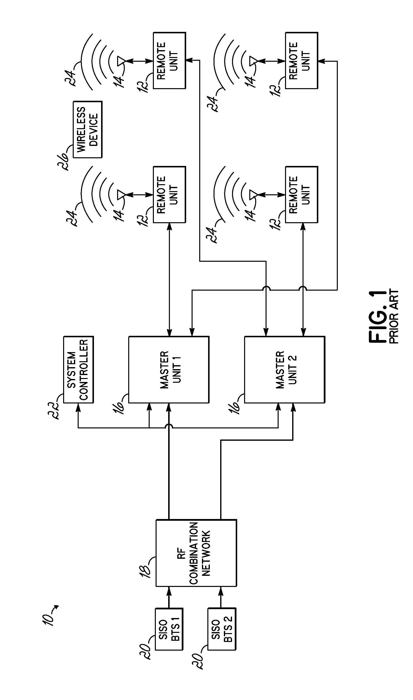
a distributed antenna and wireless technology, applied in multiplex communication, site diversity, phase-modulated carrier systems, etc., can solve the problems of signal degradation and collision, significant increase in system capacity, and system illustrated in fig. 1 cannot take advantage of mimo technology

Active Publication Date: 2013-07-25
ANDREW WIRELSS SYST
View PDF52 Cites 102 Cited by
  • Summary
  • Abstract
  • Description
  • Claims
  • Application Information

AI Technical Summary

Problems solved by technology

This may lead to a significant increase in the system capacity.
Generally, the systems illustrated in FIG. 1 cannot take advantage of MIMO technology.
The wireless signals 24 from each remote unit are typically at the same frequency and carry the same data, and communication between a plurality of remote units 12 and the wireless device 26 simultaneously may result in signal degradation and collisions.

Method used


Image

  • Distributed antenna system for MIMO signals
  • Distributed antenna system for MIMO signals
  • Distributed antenna system for MIMO signals

Examples


Embodiment Construction

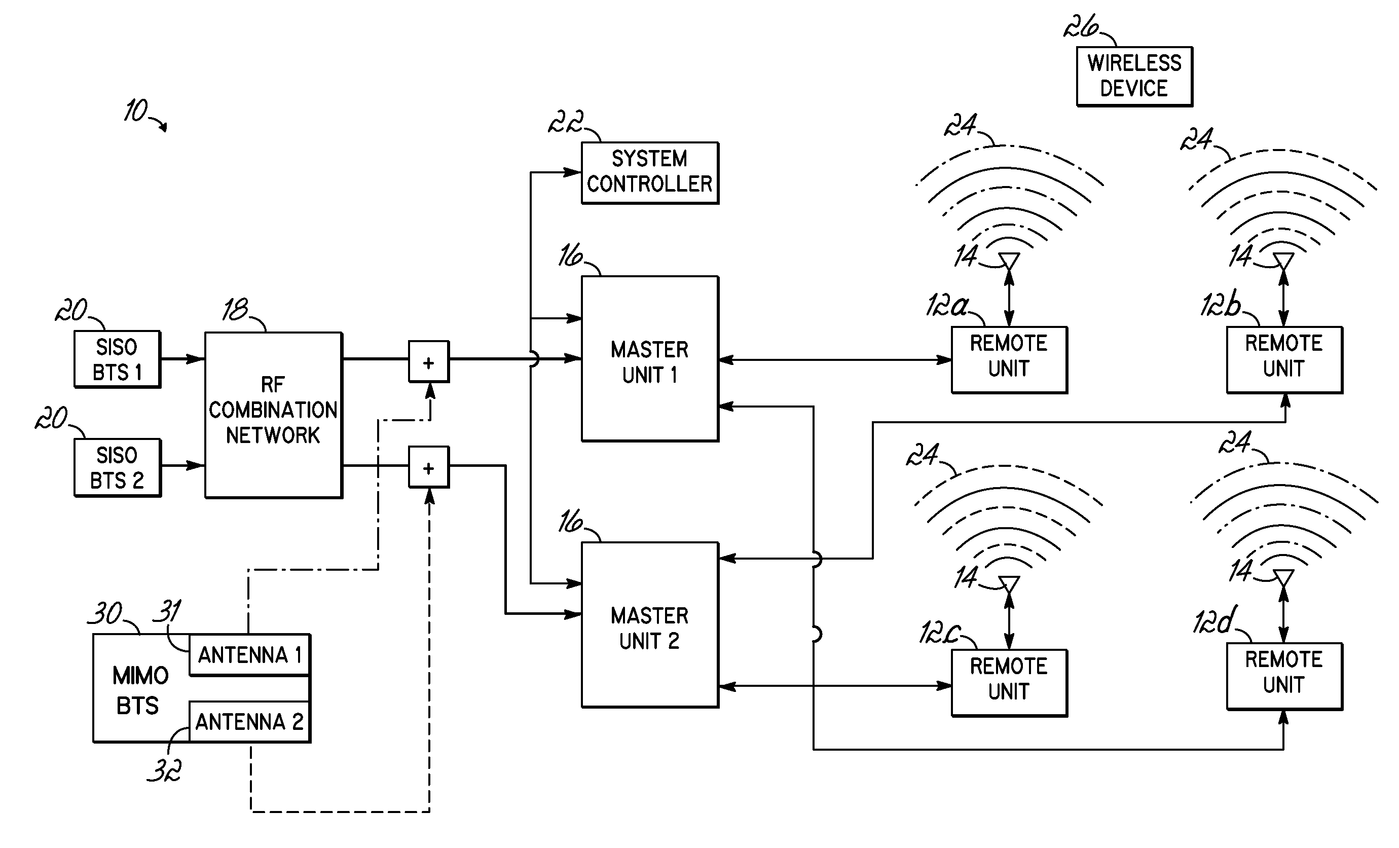
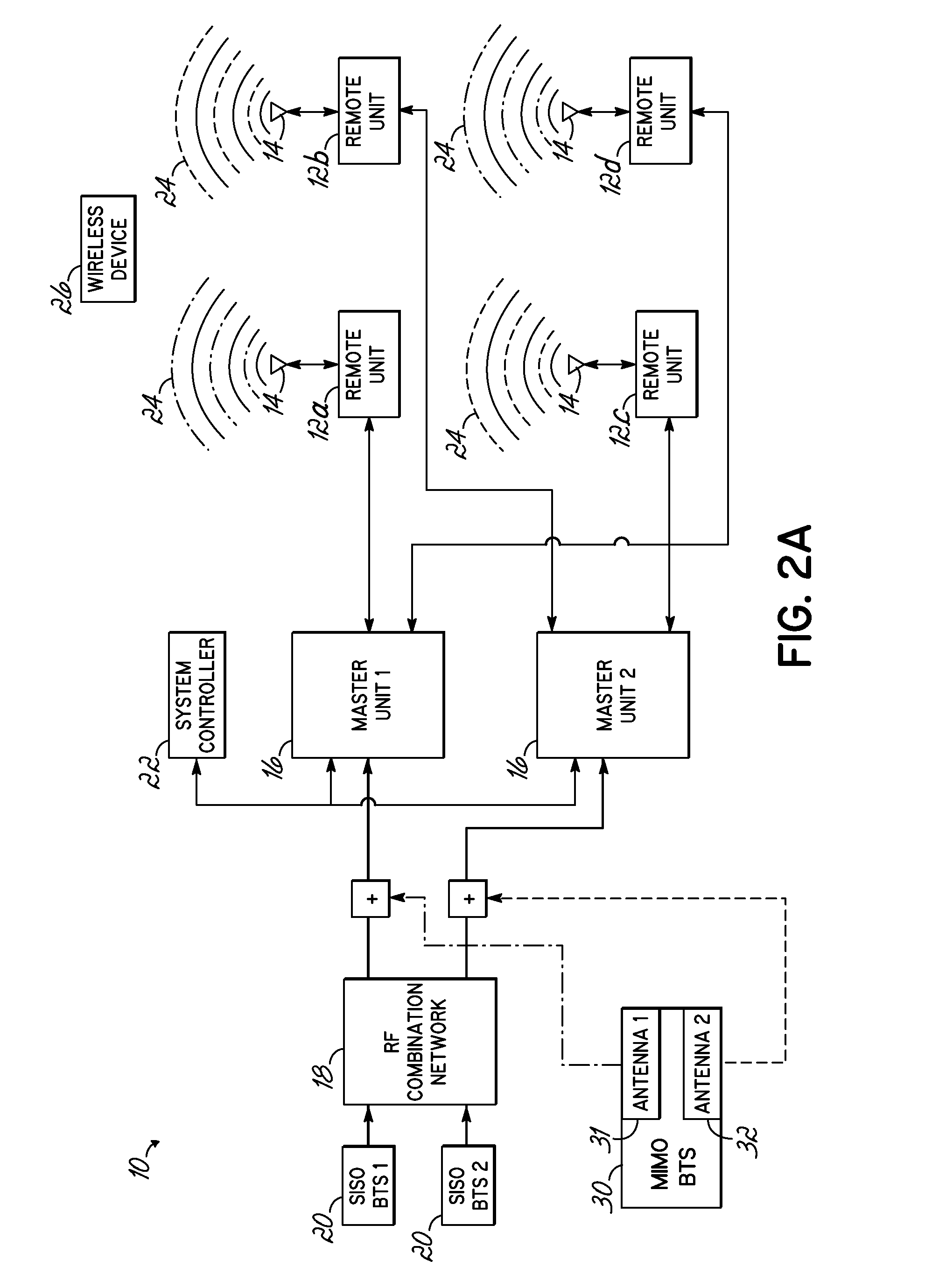
[0025]FIG. 2A illustrates a schematic view of one possible implementation of a MIMO system, wherein a MIMO base station is incorporated with a distributed antenna system, such as that shown in FIG. 1. With respect to FIG. 1, like reference numerals are utilized in FIG. 2A where applicable. As illustrated, two SISO base stations 20 (each SISO base station 20 a “SISO BTS”20) are coupled with each of the remote units. Additionally, a MIMO base station 30, including antennas 31 and 32, are coupled with the remote units 12. Antenna 1 of the MIMO BTS 30 is coupled with remote units 12a and 12d through a first master unit 16 (MASTER UNIT 1). Antenna 2 of the MIMO BTS 30 is coupled with remote units 12b and 12c through as second master unit 16 (MASTER UNIT 2). As such, as illustrated by the wireless signals 24 produced at each remote unit, each master unit will transmit signals from the MIMO BTS 30, in addition to a combined signal from the combination of signals output by the SISO BTSs 20....


PUM


Abstract

A distributed antenna system includes a multiple-input and multiple-output (MIMO) base station configured to output at least a first signal and a second signal. At least one master unit communicates with the MIMO base station. At least one remote unit communicates with the master unit. At least one antenna is coupled with the remote unit for receiving signals from the remote unit. A hybrid coupler is coupled between the remote unit and antenna and is configured to receive the first signal Ch1 and the second signal Ch2 from the remote unit on respective first and second ports and to provide an output signal on at least one output port. The output signal includes at least a portion of the first signal and at least a portion of the second signal. The antenna is coupled with the output port.

Description

RELATED APPLICATIONS [0001]This Application is a continuation-in-part of U.S. patent application Ser. No. 12 / 634,212, filed Dec. 9, 2009, entitled “DISTRIBUTED ANTENNA SYSTEM FOR MIMO SIGNALS”, the application and disclosure of which is hereby incorporated by reference in its entirety as though fully disclosed herein.[0002]This Application is also a continuation of International Application No. PCT / US2011 / 062640, filed Nov. 30, 2011, entitled “DISTRIBUTED ANTENNA SYSTEM FOR MIMO SIGNALS”, which in turn, claims priority to Italian Patent Application No. 2010A000714, filed Dec. 1, 2010, entitled “DISTRIBUTED ANTENNA SYSTEM FOR MIMO SIGNALS”, the applications and disclosures of which are hereby incorporated by reference in their entireties as though fully disclosed herein.FIELD OF THE INVENTION [0003]Embodiments of the invention are directed to wireless communication systems, and specifically directed to a distributed antenna system for a wireless MIMO communications.BACKGROUND OF THE ...

Claims


Application Information

Patent Timeline
Patent Type & Authority Applications(United States)
IPC IPC(8): H04L27/20
CPCH04J14/0247H04J14/0252H04L27/20H04B7/0413H04J14/0298H04J14/028H04W88/085H04J14/0254H04B7/0682H04B7/024H04B7/0452H04L5/14H04B10/25758
Inventor TARLAZZI, LUIGIBRIGHENTI, SAMUELEFACCIN, PIER
Owner ANDREW WIRELSS SYST
Why Eureka
Try Eureka