Mobile communication method, radio terminal, and base station

a mobile communication and radio terminal technology, applied in the direction of error detection/correction, connection management, instruments, etc., can solve the problems of long time period, inability of radio terminal to and inability to always send rlf report about connection failur

Active Publication Date: 2013-07-25
KYOCERA CORP
View PDF4 Cites 51 Cited by
  • Summary
  • Abstract
  • Description
  • Claims
  • Application Information

AI Technical Summary

Benefits of technology

[0012]Thus, the present invention provides a mobile communication method, a radio terminal, and a base station by which is it possible to prevent a network from performing a wrong parameter adjustment.

Problems solved by technology

A radio terminal cannot always send an RLF report about the connection failure to the network immediately after the occurrence of a connection failure is detected.
In such cases, a long period of time may pass from the time of occurrence of a connection failure until the transmission of the RLF report.
Therefore, after performing parameter adjustment for coverage optimization, the network would mistakenly receive the RLF report about the connection failure occurring before the adjustment of parameters, and wrong parameter adjustment maybe induced.

Method used


Image

  • Mobile communication method, radio terminal, and base station
  • Mobile communication method, radio terminal, and base station
  • Mobile communication method, radio terminal, and base station

Examples


first embodiment

[0032](Overview of Mobile Communication System)

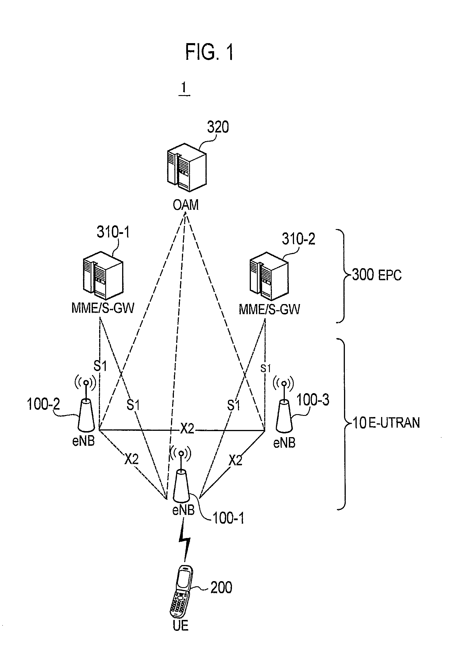
[0033]FIG. 1 is a diagram showing an entire configuration of a mobile communication system 1 according to the present embodiment. The mobile communication system 1 according to the present embodiment is configured based on LTE (Long Term Evolution) or LTE-Advanced, whose specifications are stipulated in 3GPP, and supports the above-mentioned Immediate MDT.

[0034]As shown in FIG. 1, the mobile communication system 1 includes eNB (evolved Node-B) 100, UE (User Equipment) 200, MME (Mobility Management Entity) / S-GW (Serving Gateway) 310, and OAM (Operation and Maintenance) 320. In the present embodiment, the eNB 100 corresponds to a base station, and the UE 200 corresponds to a radio terminal.

[0035]A plurality of eNBs 100 configure E-UTRAN (Evolved-UMTS Terrestrial Radio Access Network) 10, which is the radio access network of LTE. In the present embodiment, E-UTRAN 10 corresponds to a network to which the UE 200 is connected.

[0036]Each eNB ...

second embodiment

[0091]The differences in the second embodiment with respect to the first embodiment are described below.

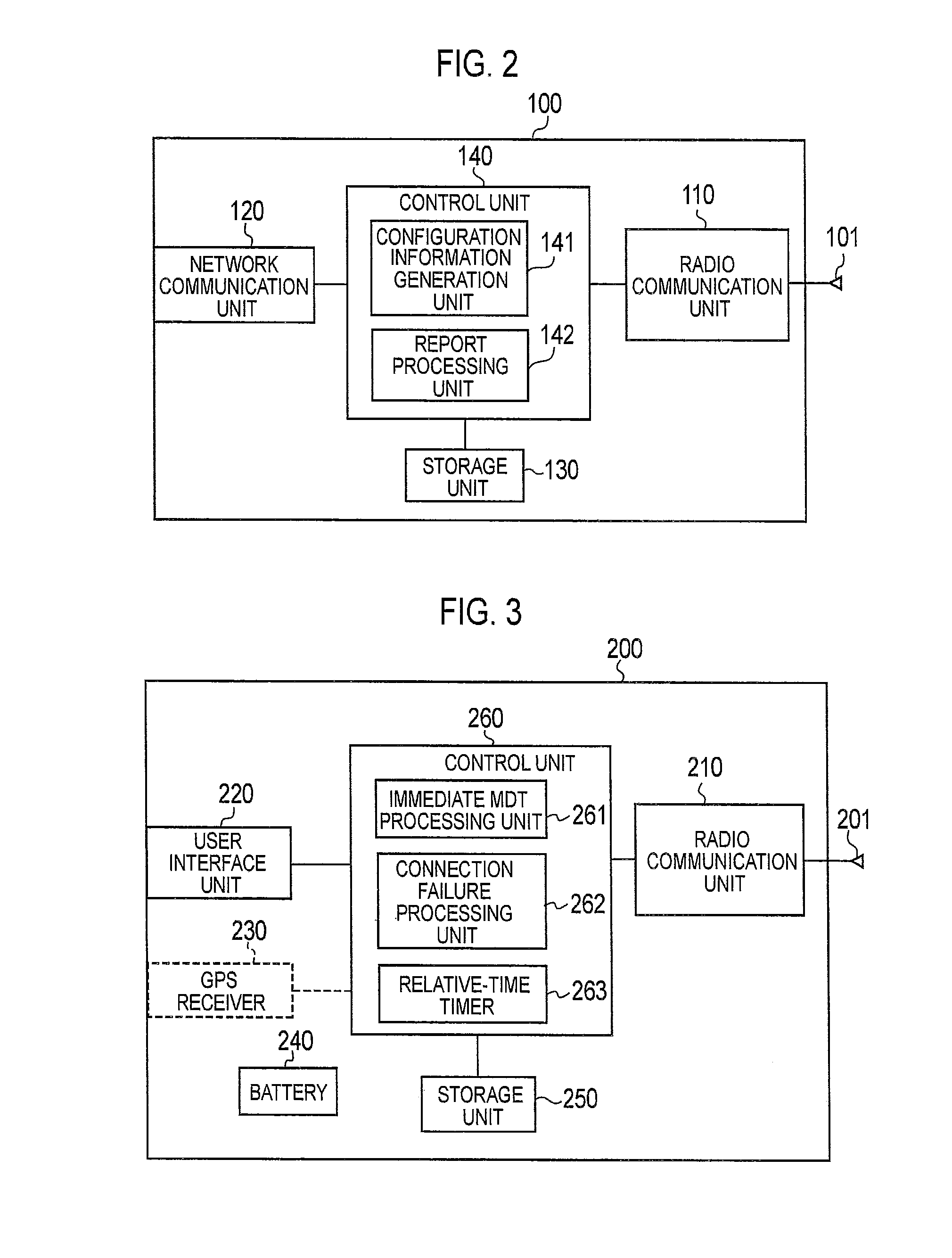
[0092]In the present embodiment, the radio communication unit 210 of the eNB 100 broadcasts the absolute time information indicating the network time. In more details, the radio communication unit 210 sends the absolute time information over the broadcast channel by including it in the system information block (SIB).

[0093](Operation of UE 200)

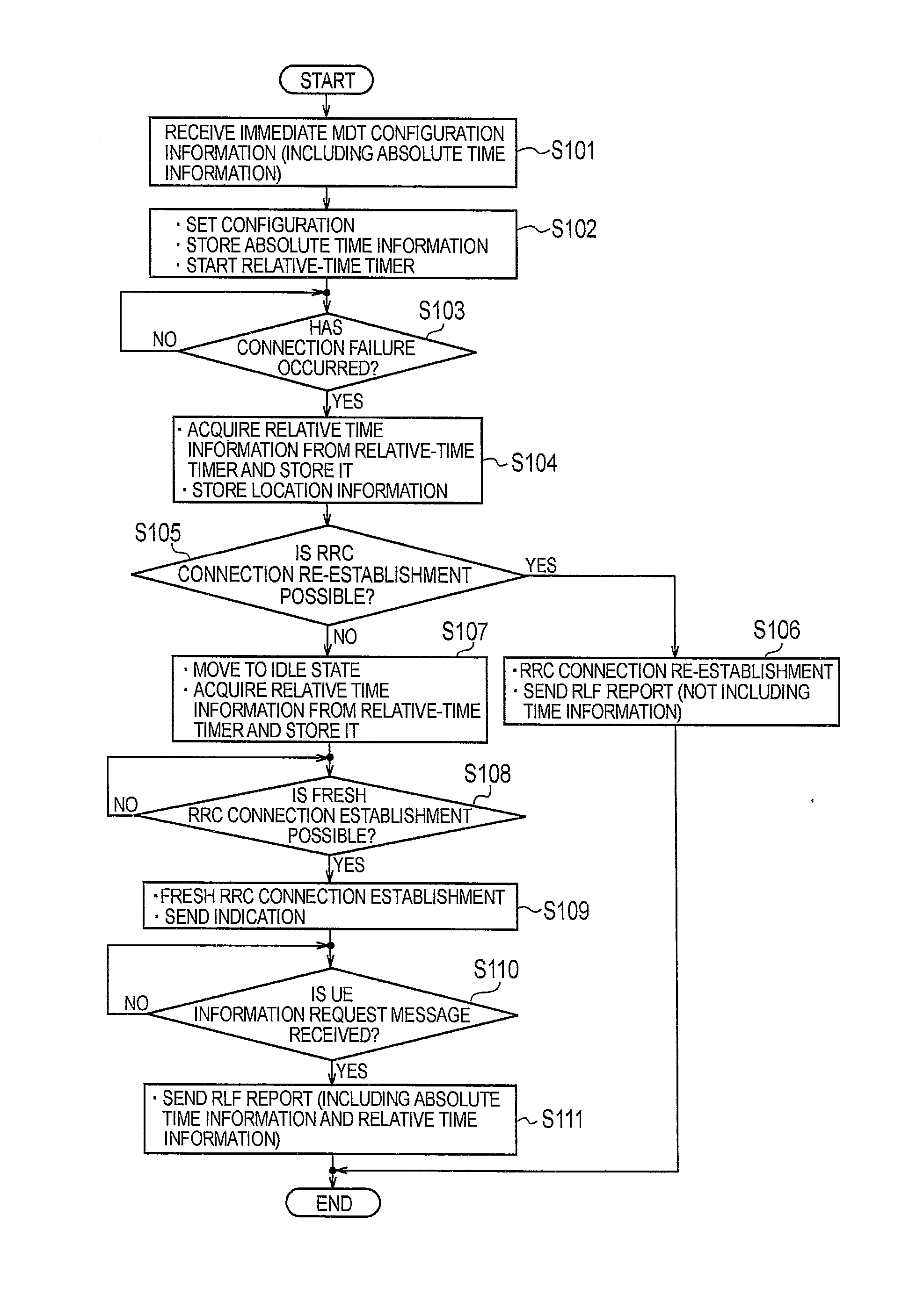
[0094]The differences in the operation of the UE 200 according to the present embodiment with respect to the first embodiment are described below. FIG. 5 is an operation flowchart of the UE 200 according to the present embodiment. In the initial state of FIG. 5, the UE 200 is assumed to be in the connected state (RRC connected state).

[0095]In step S201, the radio communication unit 210 receives the Measurement Configuration information according to Immediate MDT from the serving cell. In the present embodiment, the Measurement Configuration i...


PUM


Abstract

A mobile communication method in which a radio terminal connects to a network so as to perform a communication, comprises: a step in which the radio terminal detects an occurrence of a connection failure with the network in a connected state; and a step of sending a radio link failure (RLF) report regarding the detected connection failure, from the radio terminal to the network. In the step of sending the RLF report, the radio terminal sends time information, which is contained in the RLF report, for identifying a time of occurrence of the connection failure, to the network.

Description

TECHNICAL FIELD[0001]The present invention relates to a mobile communication method, a radio terminal, and a base station handling a radio link failure (RLF) report.BACKGROUND ART[0002]In a mobile communication system, if a building is built in the vicinity of a base station, or if the installation status of a base station in the vicinity of the base station changes, the radio communication environment according to the base station changes. Therefore, conventionally, the operators make use of a measurement vehicle in which measurement equipment is loaded, and perform a drive test by measuring a state of a signal received from the network (base station), and then collecting the measurement data.[0003]Such a measurement and collection process can, for example, contribute to the optimization of coverage of the base station, but faces the problem of too many man-hours and high cost. Thus, according to 3GPP (3rd Generation Partnership Project), i.e., a standardization project for mobile ...

Claims


Application Information

Patent Timeline
Patent Type & Authority Applications(United States)
IPC IPC(8): H04W24/04
CPCH04W24/04H04W76/046H04L1/0026H04W76/18H04W76/27G06F11/00H04W72/21H04W72/51H04L41/069H04W24/02
Inventor CHANG, HENRYFUKUTA, NORIYOSHI
Owner KYOCERA CORP
Why Eureka
Try Eureka