Control apparatus for hybrid vehicle

a control apparatus and hybrid technology, applied in the direction of vehicle sub-unit features, automatic control systems, instruments, etc., can solve the problems of inconvenient low frequency of performing the detection of battery degradation, the change of battery charge from the upper limit to the lower limit, etc., to achieve accurate and highly frequent detection of battery degradation

Active Publication Date: 2013-07-25
TOYOTA JIDOSHA KK
View PDF6 Cites 25 Cited by
  • Summary
  • Abstract
  • Description
  • Claims
  • Application Information

AI Technical Summary

Benefits of technology

[0026]In the foregoing aspect of the invention, the drive mode control portion sets the drive mode to the first mode after the charging of the electrical storage apparatus by the charger apparatus ends as the state of charge of the electrical storage apparatus reaches the first predetermined range. The determination portion performs the determination regarding degradation of the electrical storage apparatus on the basis of the data collected while the hybrid vehicle is driving in the first mode. Due to this, when the electrical storage apparatus is charged with electric power supplied from an electric power supply provided outside the hybrid vehicle, the determination regarding degradation of the electrical storage apparatus can be started. Hence, opportunities of performing the determination regarding degradation of the electrical storage apparatus can be secured. Furthermore, the drive mode control portion switches the drive mode to the second mode if, after the hybrid vehicle starts driving in the first mode, the state of charge of the electrical storage apparatus declines to the second predetermined range that is lower than the first predetermined range. Due to this, the first mode is maintained until the state of charge of the electrical storage apparatus declines to the second predetermined range that is lower than the first predetermined range. Hence, a range of the state of charge of the electrical storage apparatus for collecting data for use for the determination regarding degradation can be secured. Therefore, according to the invention, it is possible to provide a control apparatus that accurately and highly frequently detects degradation of the electrical storage apparatus mounted in the hybrid vehicle.

Problems solved by technology

However, in the hybrid vehicles as described above, it is rare that the battery charge changes from the upper limit to the lower limit.
Therefore, there is possibility that the occurrence frequency of performing the detection of degradation of the battery may become inconveniently low.

Method used


Image

  • Control apparatus for hybrid vehicle
  • Control apparatus for hybrid vehicle
  • Control apparatus for hybrid vehicle

Examples


first embodiment

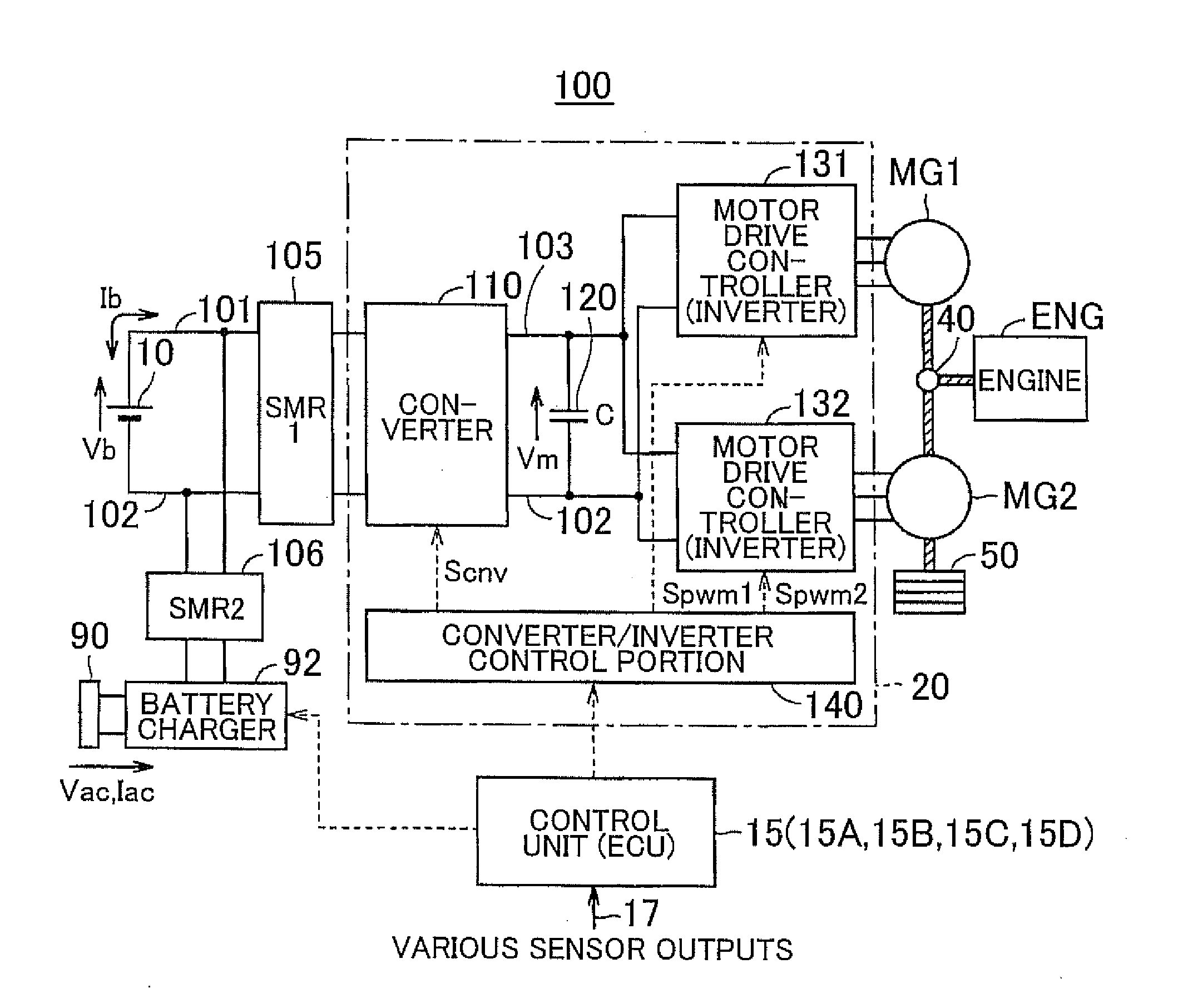
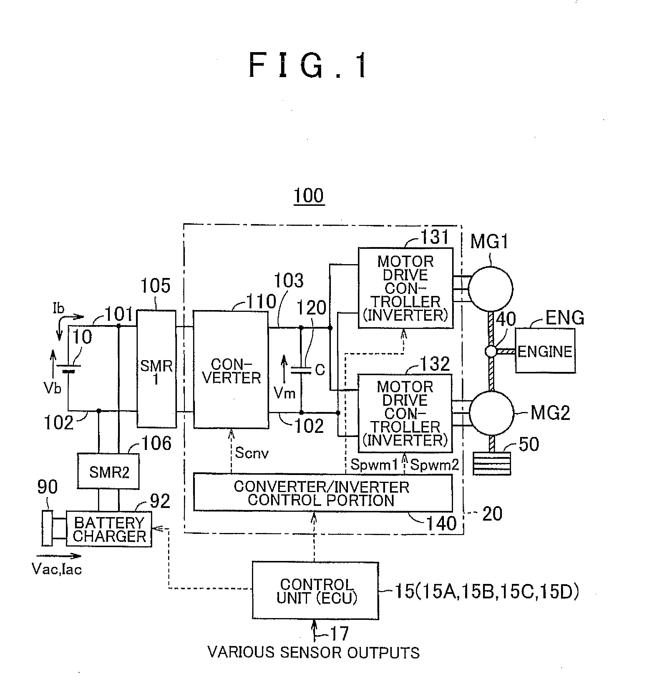
[0055]FIG. 1 is a block diagram showing an overall construction of a hybrid vehicle to which a control apparatus according to a first embodiment of the invention is applied. Referring to FIG. 1, a hybrid vehicle 100 includes a battery 10, a control apparatus 15, a PCU (Power Control Unit) 20, motor-generators MG1 and MG2, an engine ENG, a differential gear (hereinafter, also referred to as “DG”) 40, and a driving wheel 50. Furthermore, the hybrid vehicle 100 further includes a charger inlet 90, a battery charger 92 and SMRs (System Main Relays) 105 and 106. In the description below, the control apparatus 15 will also be referred to as “ECU (Electronic Control Unit) 15”.

[0056]The battery 10 is a rechargeable direct-current power supply, and is made up of, for example, a secondary battery such as a nickel metal hydride battery, a lithium-ion battery, etc. The battery 10 is electrically connected to the PCU 20, and supplies the PCU 20 with direct-current voltage. Furthermore, the batte...

second embodiment

[0111]A second embodiment of the invention is different from the first embodiment in that determination regarding degradation of the battery is performed on the basis of integrated electric power value instead of the integrated current value. In the second embodiment, the use of the integrated electric power value makes it possible to perform determination regarding decline in the frill charge capacity of the battery 10 on the basis of the energy that the battery 10 outputs. Due to this, degradation of the battery 10 mounted in the hybrid vehicle 100 can be accurately detected. Furthermore, since the electric power output from the battery 10 is used, the influence of the temperature of the battery 10 on detection accuracy can be restrained.

[0112]FIG. 6 is a functional block diagram of an ECU 15A according to the second embodiment of the invention. Referring to FIG. 6 in comparison with FIG. 2, the ECU 15A according to the second embodiment is different from the ECU 15 according to t...

third embodiment

[0125]A third embodiment of the invention is different from the first embodiment in that degradation of the battery 10 is determined on the basis of the travel distance instead of the integrated current value. In the third embodiment, the use of the travel distance makes it possible to make a determination that agrees with the degree of degradation of the battery 10 that an occupant feels.

[0126]FIG. 9 is a functional block diagram of an ECU 15B according to the third embodiment of the invention. Referring to FIG. 9 in comparison with FIG. 2, the ECU 15B according to the third embodiment is different from the ECU 15 in that a travel distance calculation portion 174 is provided instead of the current detection portion 162, the current integration portion 164, the time measurement portion 166 and the temperature detection portion 168, and in that a battery degradation determination portion 160B is different from the battery degradation determination portion 160.

[0127]The travel distanc...


PUM


Abstract

A control apparatus for a hybrid vehicle includes a drive mode control portion and a battery degradation determination portion. The chive mode control portion sets the drive mode to a CD mode after the charging of a battery by a battery charger ends as the state of charge of the battery reaches a first predetermined range. The drive mode control portion switches the drive mode to a CS mode if, after the hybrid vehicle starts driving in the CD mode, the state of charge of the battery declines to a second predetermined range that is lower than the first predetermined range. The battery degradation determination portion performs determination regarding degradation of the battery on the basis of data collected while the vehicle is driving.

Description

INCORPORATION BY REFERENCE[0001]The disclosure of Japanese Patent Application No. 2012-009689 filed on Jan. 20, 2012 including the specification, drawings and abstract is incorporated herein by reference in its entirety.BACKGROUND OF THE INVENTION[0002]1. Field of the Invention[0003]The invention relates to a control apparatus for a hybrid vehicle and, more particularly, to a control apparatus that detects degradation of an electrical storage apparatus mounted in a hybrid vehicle.[0004]2. Description of Related Art[0005]Hybrid vehicles that drive by drive force from an electric motor have a battery for storing electric power that is to be supplied to the electric motor. The battery capacity declines from full charge capacity of an initial state by various factors, including the current, voltage, temperature and SOC of the battery as well as the elapsed time, etc.. In order to determine when to replace the battery due to degradation, it is necessary to precisely detect the decline in...

Claims


Application Information

Patent Timeline
Patent Type & Authority Applications(United States)
IPC IPC(8): B60W20/00B60W10/08B60K6/442B60W10/06B60L50/16
CPCB60W20/20Y02T10/7258B60W10/08B60K6/442B60W2600/00Y10S903/93B60W20/106B60K6/445B60W10/26B60W2510/242B60W2510/244B60Y2400/214Y02T10/6286Y02T10/6239B60W10/06B60W20/13B60W2556/00Y02T10/62Y02T10/72
Inventor IZUMI, JUNTA
Owner TOYOTA JIDOSHA KK
Why Eureka
Try Eureka