
Real-time simulation of power grid disruption

a technology of power grid and real-time simulation, applied in the direction of electric devices, instruments, transportation and packaging, etc., can solve the problems of increasing the complexity of end-use models necessary to accurately forecast electricity demand, creating complex new consumption patterns, and adding significant complexity to the generation of renewable resources

Inactive Publication Date: 2013-07-25
UT BATTELLE LLC
View PDF4 Cites 155 Cited by
  • Summary
  • Abstract
  • Description
  • Claims
  • Application Information

AI Technical Summary

Benefits of technology

The invention is a system and method for detecting or predicting power grid disruptions by using advanced techniques for detecting and analyzing real-time data from multiple sources. The system automatically detects abnormal patterns in the data and predicts potential power grid disruptions, allowing for timely intervention to prevent damage or discomfort to consumers. The invention also includes methods for handling the large amount of data and multi-dimensional aspects of the data, as well as online processing of streaming data. The invention can be implemented using existing computer hardware and software. The technical effects include improved detection and prediction of power grid disruptions, improved reliability and stability of power grids, and improved resilience to unexpected events.

Problems solved by technology

National policy objectives to increase clean power generation with renewable resources will add significant complexity, requiring new classes of stochastic forecasting and control processes for the grid.
Advances in end-use efficiency will increase the complexity of end-use models necessary to accurately forecast electricity demand.
Greater use of market signals will create complex new patterns of consumption.
However, modeling these changes requires new techniques because the grid components are now more closely coupled in their responses (e.g., separating into microgrids will have decreasing validity).
Complexity of this coupling will require the next generation of scientific computing resources to solve these cases in realistic time.

Method used


Image

  • Real-time simulation of power grid disruption
  • Real-time simulation of power grid disruption
  • Real-time simulation of power grid disruption

Examples


Embodiment Construction

[0018]The present invention includes a computer-implemented method, and software for executing the method, for monitoring the electric grid and identifying issues and / or predicting failures.

[0019]The invention includes a computer system in communication with an electric power grid to receive and analyze information about the grid.

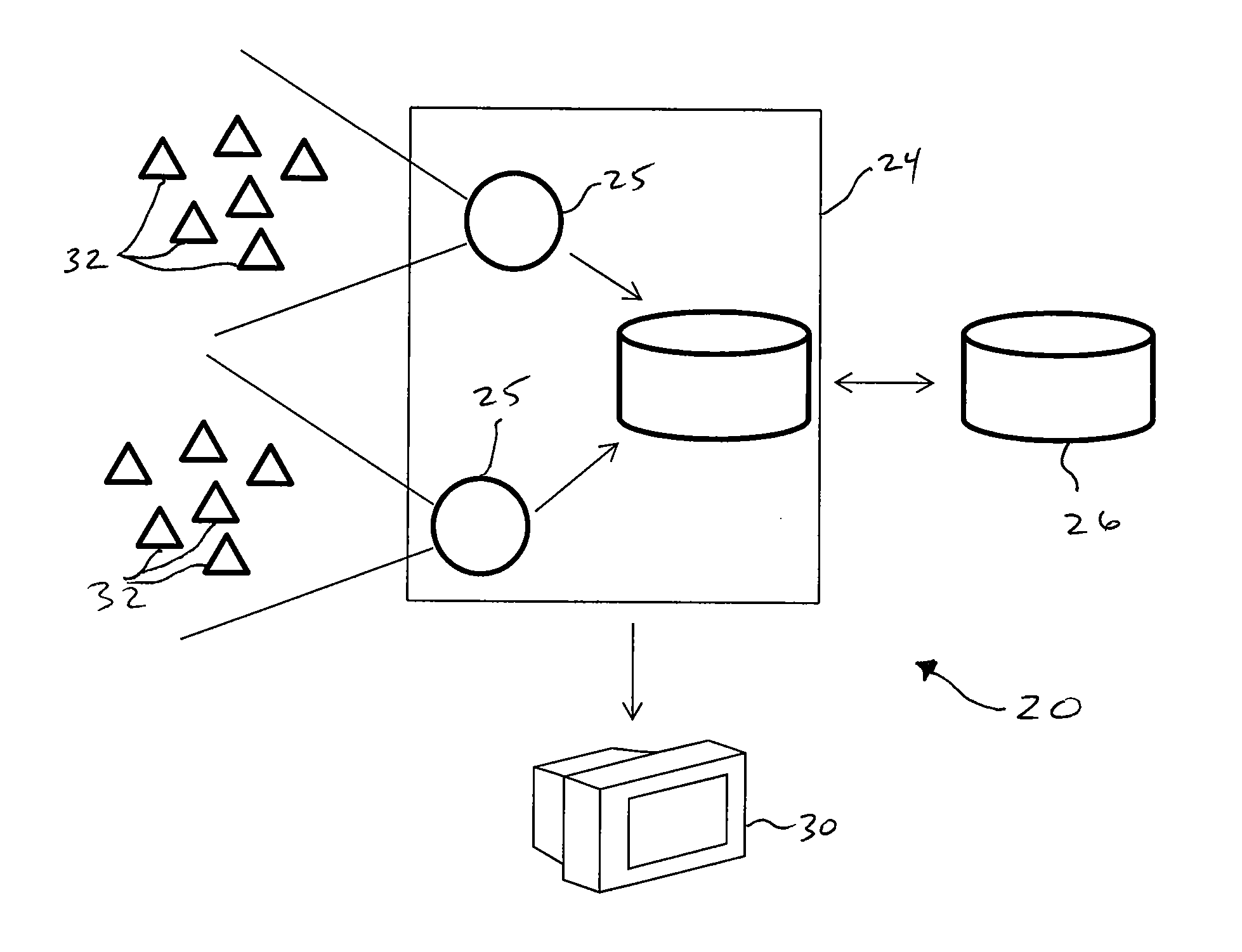
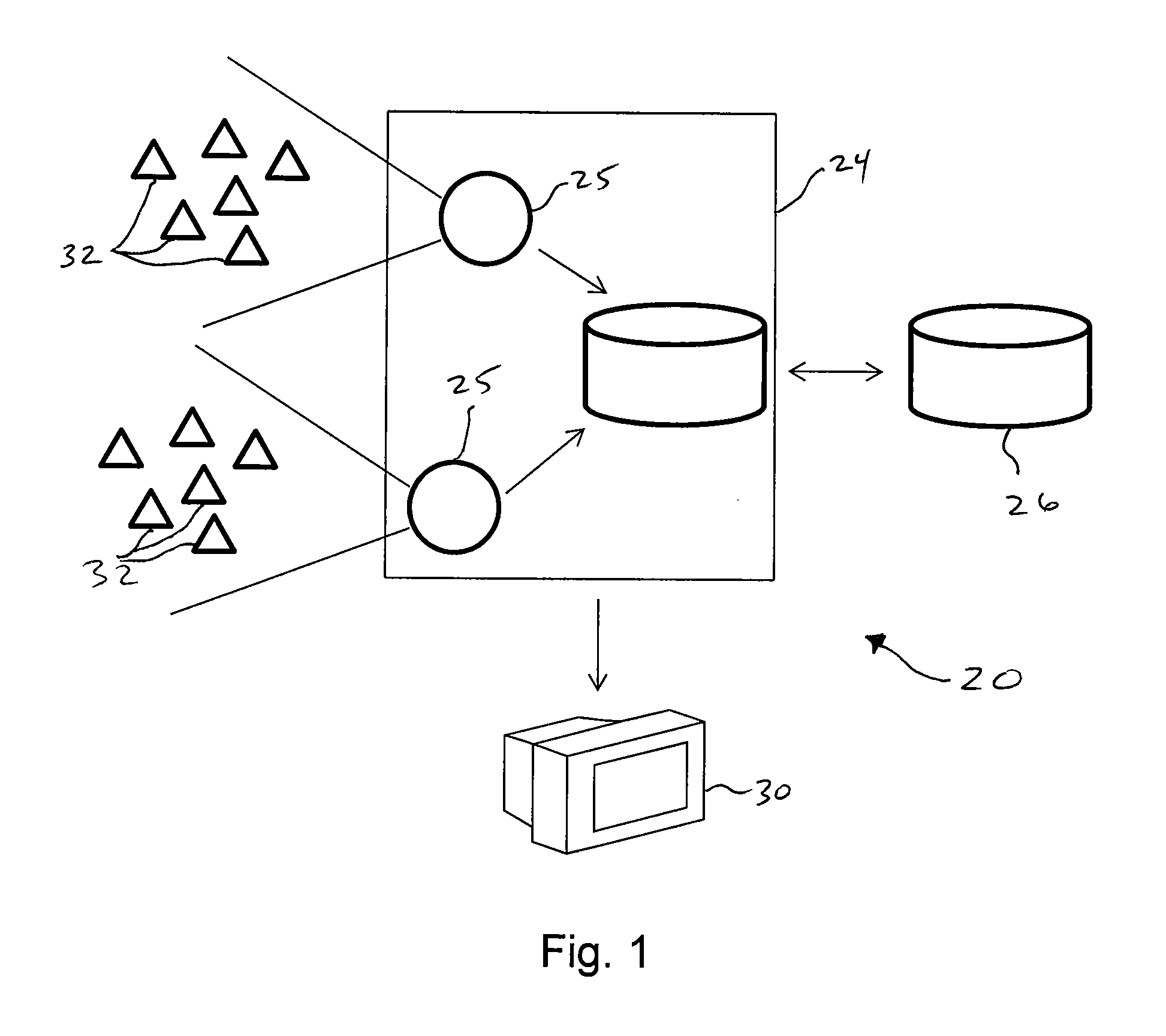
[0020]FIG. 1 representatively shows a system 20 according to one embodiment of this invention. A plurality of sensors 32 are in sensing combination with the electric grid at various remote positions. The sensors desirable continually monitor and / or measure one or more properties of the electric grid, such as, without limitation, frequency, voltage, or phase angle. In one embodiment, the sensors are a frequency measurement system designed to provide real-time measurements of frequency transients in the electric power system. Various numbers and types of sensors can be used, depending on need. In one embodiment within the scope of this invention, the sensors ...


PUM


Abstract

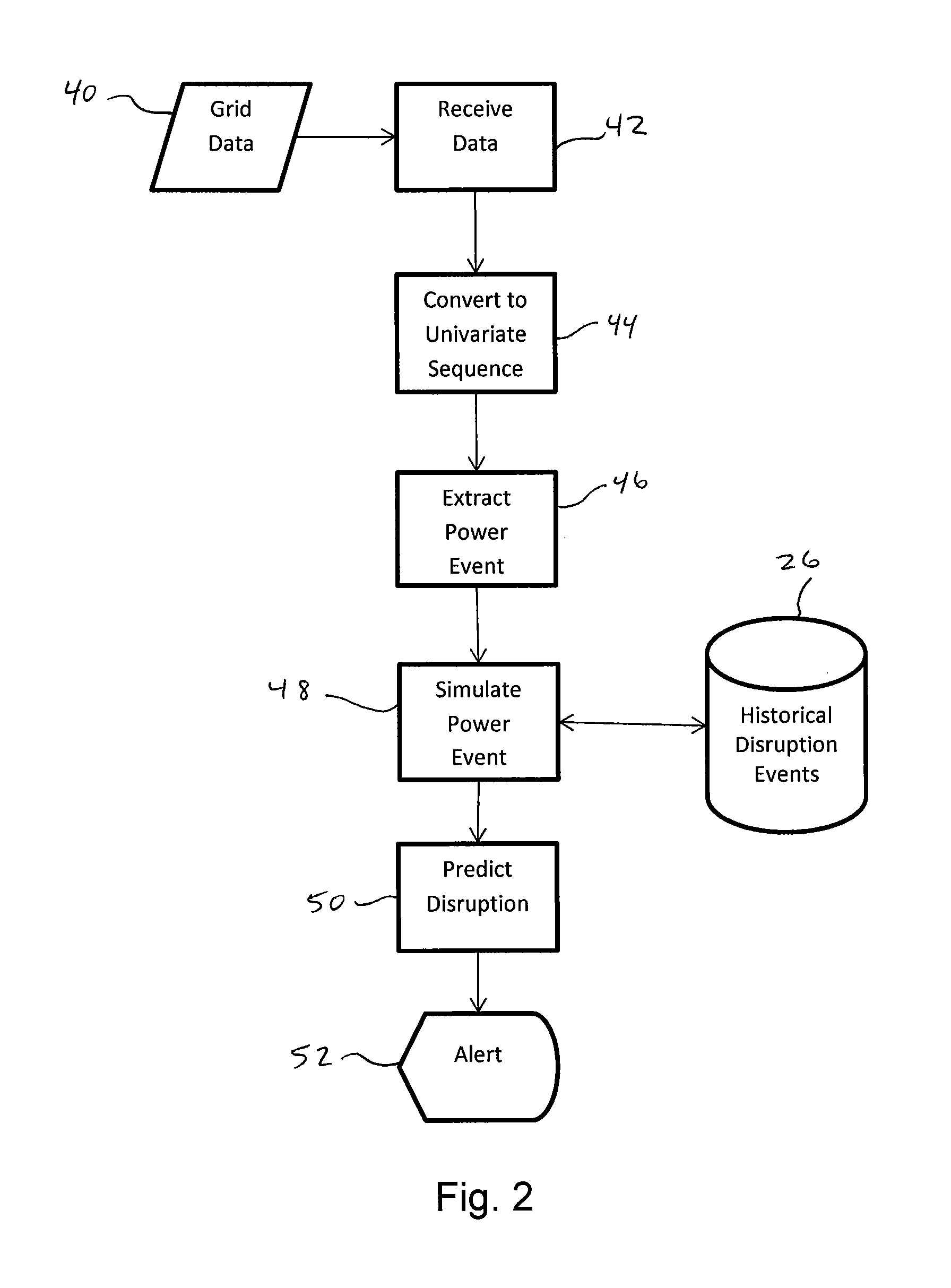
A method and system for monitoring the electric grid and predicting failures and / or other issues. Streams of data about a power grid are received from a plurality of remote power grid sensors and converted into a univariate time sequence. Anomaly patterns are identified in the univariate time sequence and analyzed or simulated to predict the power grid disruption. The anomaly patterns are compared to power disruption contingencies stored in a database to simulate and / or predict the present or future power disruption represented by the anomaly pattern.

Description

CROSS REFERENCE TO RELATED APPLICATION[0001]This application claims the benefit of U.S. Provisional Patent Application Serial No. 61 / 589,419, filed on 23 Jan. 2012. The co-pending Provisional Application is hereby incorporated by reference herein in its entirety and is made a part hereof, including but not limited to those portions which specifically appear hereinafter.GOVERNMENT RIGHTS[0002]This invention was made with government support under Contract No. DE-AC05-00OR22725 awarded by the U.S. Department of Energy. The government has certain rights in the invention.FIELD OF THE INVENTION[0003]The present invention relates to a computer-implemented method, and software for executing the method, for understanding and responding to the status, both observed and predicted, of the electric grid, and more particularly to monitoring the electric grid and predicting failures and / or other issues.BACKGROUND OF THE INVENTION[0004]The U.S. electric power system includes multiple distinct inter...

Claims


Application Information

Patent Timeline
Patent Type & Authority Applications(United States)
IPC IPC(8): G06F17/00G01R21/00
CPCH02J2003/007G06F17/00G01R21/00Y02E60/76G06Q50/06Y04S40/22G01R31/088H02J2203/20Y02E60/00Y04S40/20
Inventor FERNANDEZ, STEVEN J.SHANKAR, MALLIKARJUNNUTARO, JAMES J.LIU, YILUDIMITROVSKI, ALEKSANDAR D.OMITAOMU, OLUFEMI A.GROER, CHRISTOPHER S.SPAFFORD, KYLE L.VATSAVAI, RANGA R.
Owner UT BATTELLE LLC
Learn More