Earth/ground clamp for measuring earth resistance of electrical installations

a technology of earth/ground clamping and electrical installations, which is applied in the direction of electric digital data processing, complex mathematical operations, instruments, etc., can solve the problems of difficult use of additional testing means, rapid increase in the circulation of electric current within the human body, irremediable damage, etc., and achieves the effect of convenient and quick us

Active Publication Date: 2013-07-25
CHAUVIN ARNOUX & CIE
View PDF9 Cites 25 Cited by
  • Summary
  • Abstract
  • Description
  • Claims
  • Application Information

AI Technical Summary

Benefits of technology

[0008]Therefore, by determining the contact voltage (the potential of the measurement point relative to earth) directly at the earth clamp without measuring the same, it is possible firstly to ensure true safety for persons that is much higher

Problems solved by technology

These leakage currents of greater or lesser magnitude are not without safety problems for service engineers carrying out an electrical installation or testing an installation, and who are in contact with the equipment connected to the protective conductor.
In addition, over and above a given voltage, which varies depending on surroundings and the

Method used


Image

  • Earth/ground clamp for measuring earth resistance of electrical installations
  • Earth/ground clamp for measuring earth resistance of electrical installations
  • Earth/ground clamp for measuring earth resistance of electrical installations

Examples


Embodiment Construction

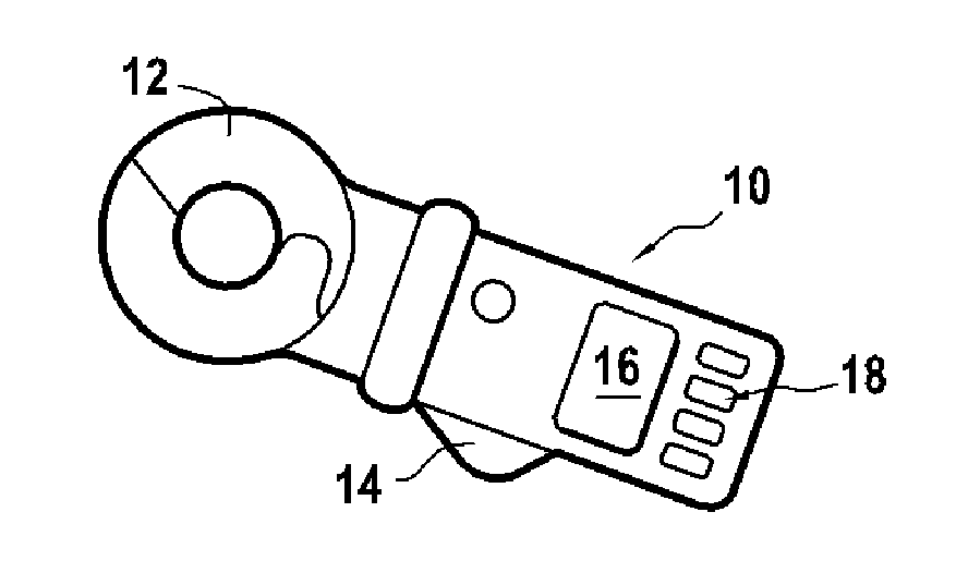
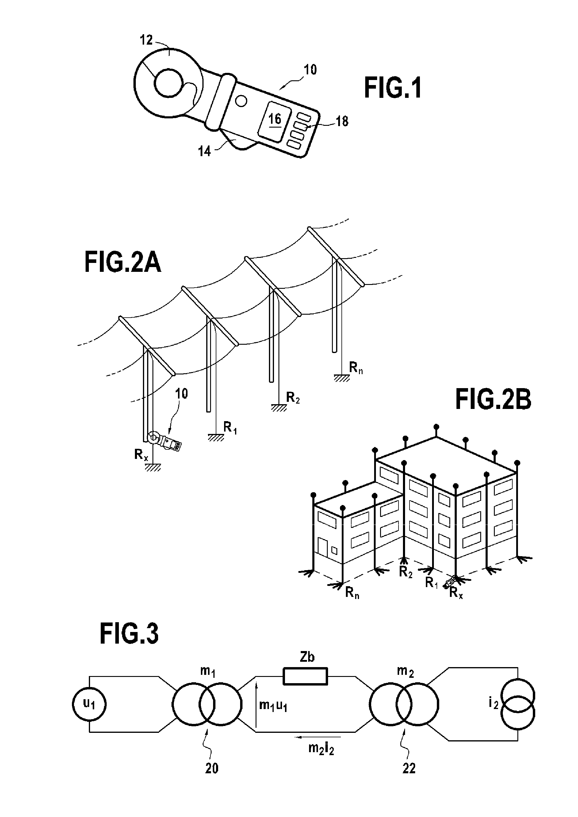
[0022]As shown in FIG. 1, an earth clamp 10 is a portable device which an operator can hold in one hand for easy and quick testing of the earth connection of electric installations or electric cable pylons such as those illustrated in FIGS. 2A and 2B. Contrary to traditional devices, measurement using an earth clamp does not require the planting of auxiliary stakes or the opening of an earth connection (earth bar for example) insulating the electric installation.

[0023]The earth clamp has a jaw 12 which can be opened by a handle 14 and can be clamped round the earthed conductor whose earth impedance Zx it is desired to measure. The earth clamp further comprises a display screen 16 to visualize the parameters and measurement results, and different operating buttons 18 required for use thereof.

[0024]The principle of measurement using an earth clamp is schematically illustrated in FIG. 3, which shows the ideal equivalent schematic (perfect model in which instant power is preserved and i...


PUM


Abstract

An earth clamp for testing contact voltage, comprising a measuring circuit formed of a voltage inducing transformer and a current measuring transformer, adapted to be mutually coupled by an earth conductor whose earth impedance is to be measured, a microcontroller to deliver an alternating voltage to the voltage inducing transformer and, in response, to receive a reference voltage generated in the earth conductor and an earth current iB+iF induced in the current measuring transformer, the microcontroller being configured to extract an amplitude E of the reference voltage, an amplitude IB and an amplitude IF of the earth current and a phase shift φ between the reference voltage and the loop current iB and to calculate the earth impedance Zb at a determined frequency, the microcontroller also computing the contact voltage Uc at said determined frequency by the product of the earth impedance times the amplitude IF.

Description

FIELD OF THE INVENTION[0001]The invention concerns the measurement of earth resistance of electrical installations by means of a testing device known as an earth (or ground) clamp.PRIOR ART[0002]The measurement of earth resistance using an earth clamp clamped around the conductor to be measured and using two separate transformers, one to inject a voltage into the loop and the other to measure the resulting current, is well known. Said measurement, which does not require the planting of auxiliary stakes, is particularly suitable when the electrical installation has multiple earth connections in parallel, forming several successive earth loops.[0003]Therefore, mere clamping of the earthed conductor allows the testing of the quality of the earth connection by measuring the impedance of the earth loop, and allows the value of the leakage current to be measured which circulates from the electric installation to earth.[0004]These leakage currents of greater or lesser magnitude are not wit...

Claims


Application Information

Patent Timeline
IPC IPC(8): G01R19/00G06F17/12
CPCG01R19/0007G01R27/20G06F17/12
Inventor LEGROS, PHILIPPE
Owner CHAUVIN ARNOUX & CIE
Why Eureka
Try Eureka