Pneumatic tire

a pneumatic tire and tire body technology, applied in the field of pneumatic tires, can solve the problems of poor drainage performance, unsatisfactory wear resistance, wet performance degradation, etc., and achieve the effect of reducing the risk of slipping

a pneumatic tire and tire body technology, applied in the field of pneumatic tires, can solve the problems of poor drainage performance, unsatisfactory wear resistance, wet performance degradation, etc., and achieve the effect of reducing the risk of slipping

US20130192731A1Active Publication Date: 2013-08-01SUMITOMO RUBBER IND LTD

Image

  • Pneumatic tire
  • Pneumatic tire
  • Pneumatic tire

Examples


examples

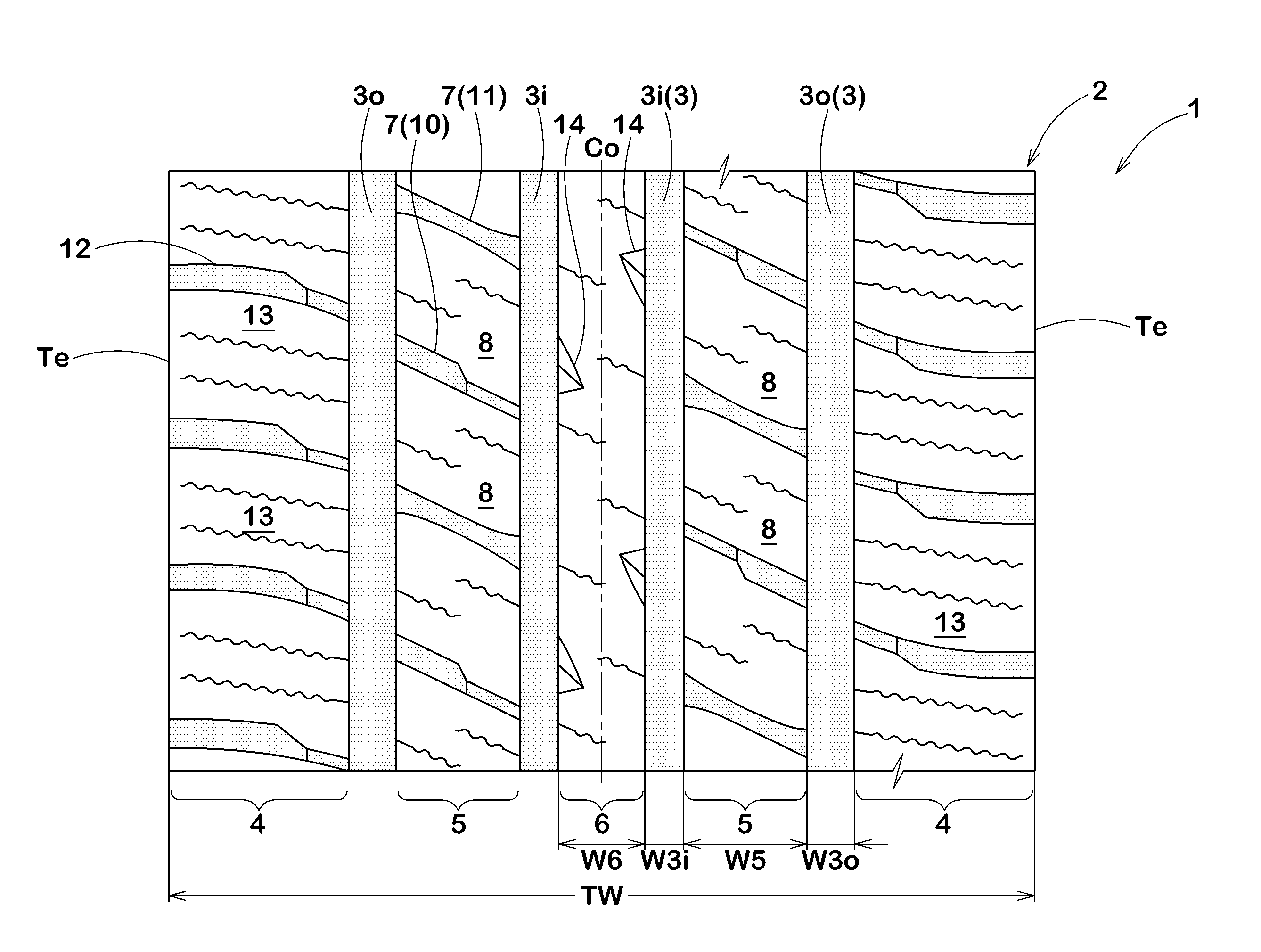
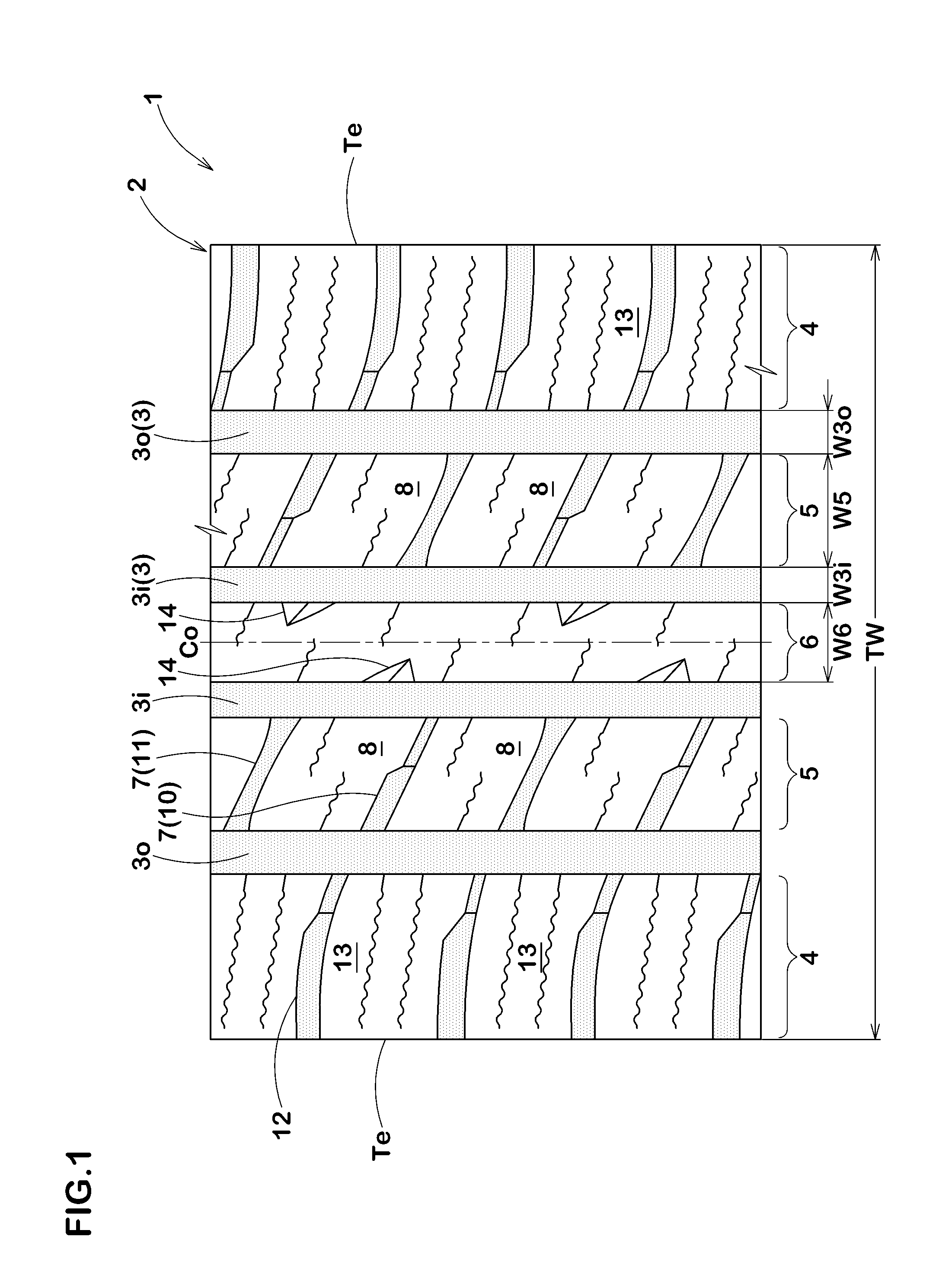
[0078]Tires with a size of 265 / 70R16 having the tread pattern in FIG. 1 as a basic pattern were prototyped according to the specifications in Table 1. The noise performance, wet performance, and uneven wear resistance was tested and evaluated for each sample tire. Note that comparisons were made with a tire having the tread pattern in FIG. 7 as a comparative example 5. Except the specifications listed in Table 1, the tires had substantially identical specifications. Shown below are common specifications:[0079]Groove width w3i of the inner circumferential main grooves=9 mm, groove depth H3i=9.5 mm[0080]Groove width w3o of the outer circumferential main grooves=11 mm, groove depth H3o=9.5 mm[0081]Land portion width W6 of the center land portion=20 mm[0082]Land portion with W5 of the inner land portions=29 mm[0083]Tread ground-contact width TW=202 mm

(1) Noise Performance

[0084]A sample tire was mounted on all wheels of a vehicle (SUV vehicle, 4000 cc) with a rim (7.0 JJ) and internal pr...


PUM


Abstract

A tread portion of a pneumatic ti re includes inner land portions between outer circumferential main grooves disposed most on tread ground-contact end sides and at least one inner circumferential main groove on the inner side thereof. The inner land portions are divided into inner blocks by inner lateral grooves inclined at an angle α of 10 to 40°. The inner lateral grooves consist of first inner lateral grooves and second inner lateral grooves which are alternately arranged in a circumferential direction. The first inner lateral grooves include a wide-width part connecting to the outer circumferential main groove and a narrow-width part connecting to the inner circumferential main groove.

Description

BACKGROUND OF THE INVENTION[0001]1. Field of the Invention[0002]The present invention relates to a pneumatic tire with improved noise performance and uneven wear resistance, without deteriorating drainage performance.[0003]2. Description of the Related Art[0004]As a pneumatic tire with improved wear resistance and drainage performance, Japanese Patent Application Publication No. 2001-206020 describes a pneumatic tire having a tread pattern as shown in FIG. 7. This tire includes, in a tread portion a, five circumferential main grooves b, for example, including outer circumferential main grooves b1 which are disposed most on tread ground-contact ends Te and inner circumferential main grooves b2 which are adjacent to the outer circumferential main grooves b1 axially inwardly with this, outer land portions c1 are formed on axially outer sides of the outer circumferential main grooves b1, inner land portions c2 are formed between the inner and outer circumferential main grooves b1, b2, a...

Claims


Application Information

Patent Timeline
01 Aug 2013
Publication
US20130192731A1
IPC
B60C11/03
CPC
B60C11/0306; B60C2011/0353; B60C2011/1213; B60C2011/0372; B60C2011/0365; B60C2011/0369; B60C2011/0383; B60C2011/0341
Inventors
OJI, TAKUYA