Laminated piezoelectric device

a piezoelectric device and piezoelectric technology, applied in piezoelectric/electrostrictive device details, piezoelectric/electrostrictive/magnetostrictive devices, piezoelectric/electrostriction/magnetostriction machines, etc., can solve problems such as polarization caused by pyroelectric effect, decreased polarization, and increased polarization. , to achieve the effect of preventing moisture intrusion, preventing migration

Active Publication Date: 2013-08-01
TDK CORPARATION
View PDF23 Cites 5 Cited by
  • Summary
  • Abstract
  • Description
  • Claims
  • Application Information

AI Technical Summary

Benefits of technology

[0023]In the present invention, the insulation layer covers at least the above portion of which the internal electrodes are exposed on the surface of the device body. With this, it enables to prevent a moisture intrusion from outside, and also enables to prevent migration generated between internal electrodes having different polarities with high reliability.
[0024]Further, in the present invention, a resistance layer, which electrically connects across the external electrodes having different polarities, is formed separately from the insulation layer. The electric resistance value of this resistance layer is lower than the insulation layer. With this, even if a polarization is generated in a direction opposite to a spontaneous polarization when the piezoelectric device according to the present invention is in lowering of temperature, it enables to discharge the generated electrical charge through the resistance layer with high reliability. As a result, with the piezoelectric device according to the present invention, it enables to suppress the decrease of polarizability even if it is placed in an environment in which the temperature change generates.
[0025]In this way, it enables to obtain a highly reliable laminated piezoelectric device by preventing migration with insulation layer and suppressing the decrease of polarizability with resistance layer.
[0026]Preferably, the resistance layer does not contact with the first internal electrode and the second internal electrode. With this, it enables to completely prevent a short circuit through the resistance layer. The resistance layer may cover a portion of the surface of the insulation layer.
[0027]Preferably, the resistance layer covers at least a portion of the first external electrode and / or the second external electrode. With this, the resistance layer and the external electrodes are physically and electrically connected with high reliability. Therefore, a junction of the resistance layer and the external electrode becomes strong by anchor effect. Further, it enables to discharge an electrical charge generated by pyroelectric effect with high reliability.

Problems solved by technology

Further, for instance, if such piezoelectric device is applied to portable electronic devices and the like, it will be exposed to temperature changes due to surrounding environmental changes.
If the piezoelectric device is exposed to such temperature changes, polarization caused by pyroelectric effect becomes a problem.
This decreased polarizability does not recover even if the temperature rises again.
Therefore, there is a problem that the characteristics deteriorate since the polarizability gradually decreases and a desired displacement cannot be obtained, when the process of lowering of temperature is repeated.
However, for making a resistance value of the exterior material in the range that could prevent migration and suppress the decrease of polarizability, there is a problem that it is difficult to adjust the resistance value since fluctuation of resistance value of resin composing the exterior materials and the content of conductive particles and the like should be taken into consideration.
When the conductive particles aggregate in the exterior materials, there were problems that the resistance value of the aggregated portion locally decreases and then a short circuit might be caused through the portion.
Particularly, this problem becomes prominent as the distance (thickness of piezoelectric layer) between internal electrodes gets smaller.
Further, there is a possibility that it might be unable to adequately prevent moisture permeation if providing several functions to the exterior materials.
Furthermore, when a substrate of the piezoelectric devices is cut after firing to obtain individual piezoelectric devices, there were problems that fluctuation of resistance value might be generated since the broken internal electrodes extend along a penetration direction of cutting blades.

Method used


Image

  • Laminated piezoelectric device
  • Laminated piezoelectric device
  • Laminated piezoelectric device

Examples


Embodiment Construction

[0034]The followings are explanation of embodiments of the present invention based on Figures.

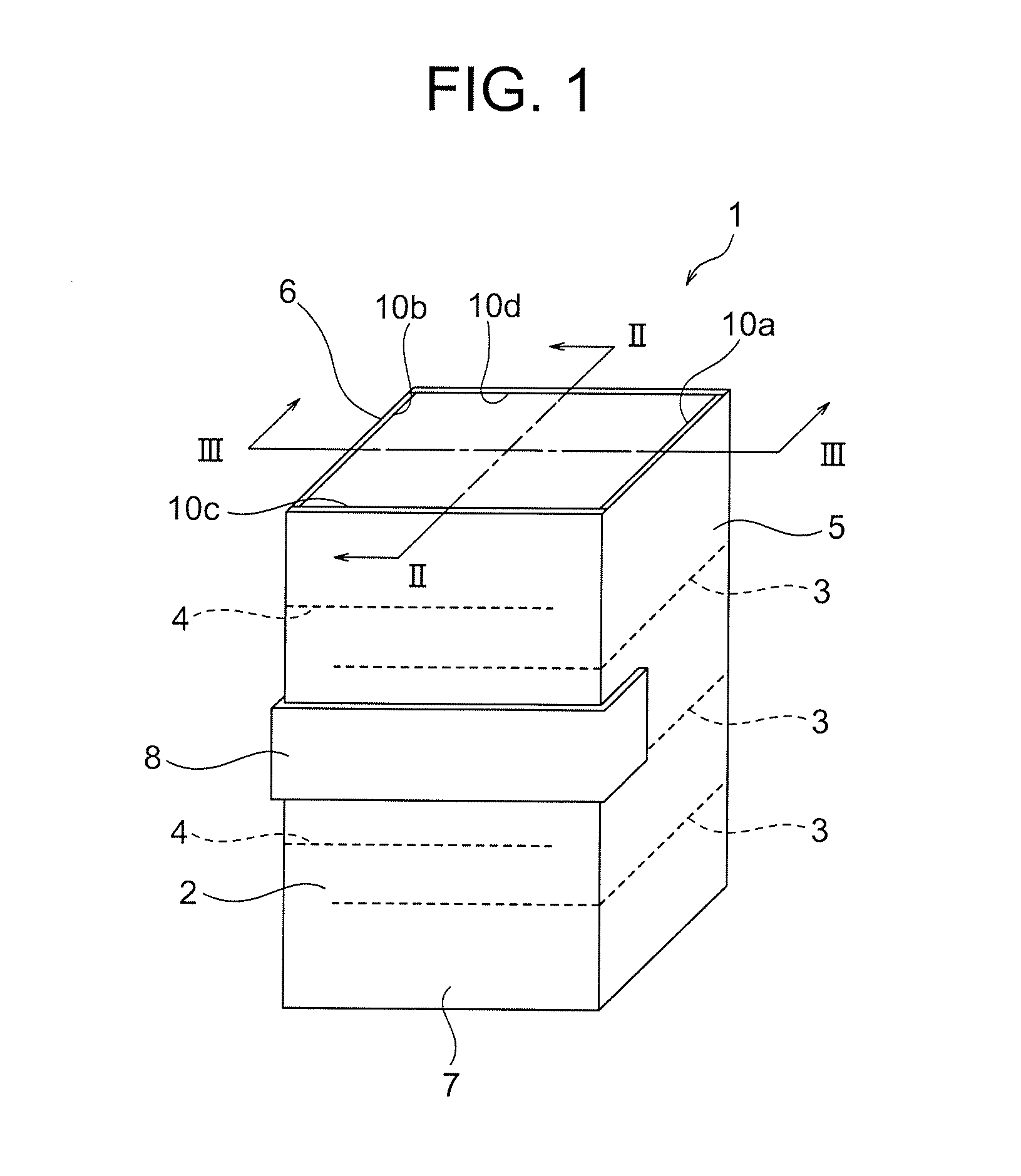
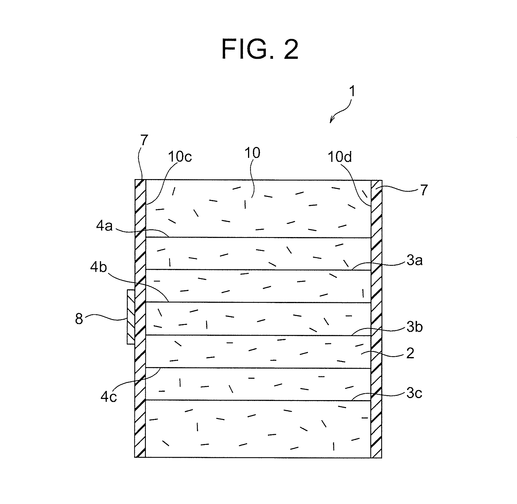
[0035]As shown in FIGS. 1 and 2, a laminated piezoelectric device 1 according to the present embodiment comprises a quadrangular-prism-shaped device body 10 having a configuration that piezoelectric layers 2 and internal electrodes 3, 4 are alternately laminated. On the two opposing sides 10a, 10b of this device body 10, external electrodes are formed respectively. Specifically, a first external electrode 5 is formed on the side 10a and a second external electrode 6 having different polarities from the first external electrode 5 is formed on the side 10b.

[0036]Further, on the opposing sides 10c, 10d, which is different from the sides 10a, 10b on which external electrodes 5, 6 are formed, edge portions of internal electrodes 3, 4 are exposed and insulation layers 7 are formed respectively thereon. Further, on the surface of the insulation layer 7 of at least either one, the resistance layer...


PUM

PropertyMeasurementUnit
thicknessaaaaaaaaaa
electric resistanceaaaaaaaaaa
thicknessaaaaaaaaaa

Abstract

A laminated piezoelectric device comprising a device body 10 on which a number of piezoelectric layers 2 and internal electrodes 3, 4 are laminated, external electrodes 5, 6 electrically connected to the internal electrodes 3, 4 and formed on the surface of the device body 10, an insulation layer 7 and a resistance layer 8. The insulation layer 7 covers at least a portion wherein internal electrodes 3, 4 are exposed on the surface of the device body 10, where mechanical displacement is generated by applying voltage. The resistance layer 8 is formed to connect between external electrodes 5, 6 and has a lower electric resistance value than the insulation layer 7.

Description

BACKGROUND OF THE INVENTION[0001]1. Field of the Invention[0002]The present invention relates to a laminated piezoelectric device. More specifically, it relates to a laminated piezoelectric device which enables both prevention of migration and suppression of characteristic deterioration caused by pyroelectric effect.[0003]2. Description of the Related Art[0004]A piezoelectric device is a device mutually converting mechanical displacement and electric displacement by utilizing piezoelectric effect and inverse piezoelectric effect. Such piezoelectric device can be obtained by forming and firing piezoelectric ceramics to make a device body, and then forming electrodes thereon and applying direct electric fields to uniform a direction of spontaneous polarization.[0005]The mechanical displacement obtained by the piezoelectric device is minute. Therefore, the piezoelectric device is used for various products as actuators for the purpose that accurate and precise controls are required, for...

Claims


Application Information

Patent Timeline
Patent Type & Authority Applications(United States)
IPC IPC(8): H01L41/047
CPCH01L41/0471H01L41/083H01L41/04H10N30/80H10N30/50H10N30/871
Inventor OZAWA, SATOSHIITOH, SYUUZITAGUCHI, HARUO
Owner TDK CORPARATION
Why Eureka
Try Eureka