
System and method for capturing dust created by rotary tool attachments

Inactive Publication Date: 2013-08-08
SKITTER & SQUIRT ADVENTURES
View PDF6 Cites 12 Cited by
  • Summary
  • Abstract
  • Description
  • Claims
  • Application Information

AI Technical Summary

Benefits of technology

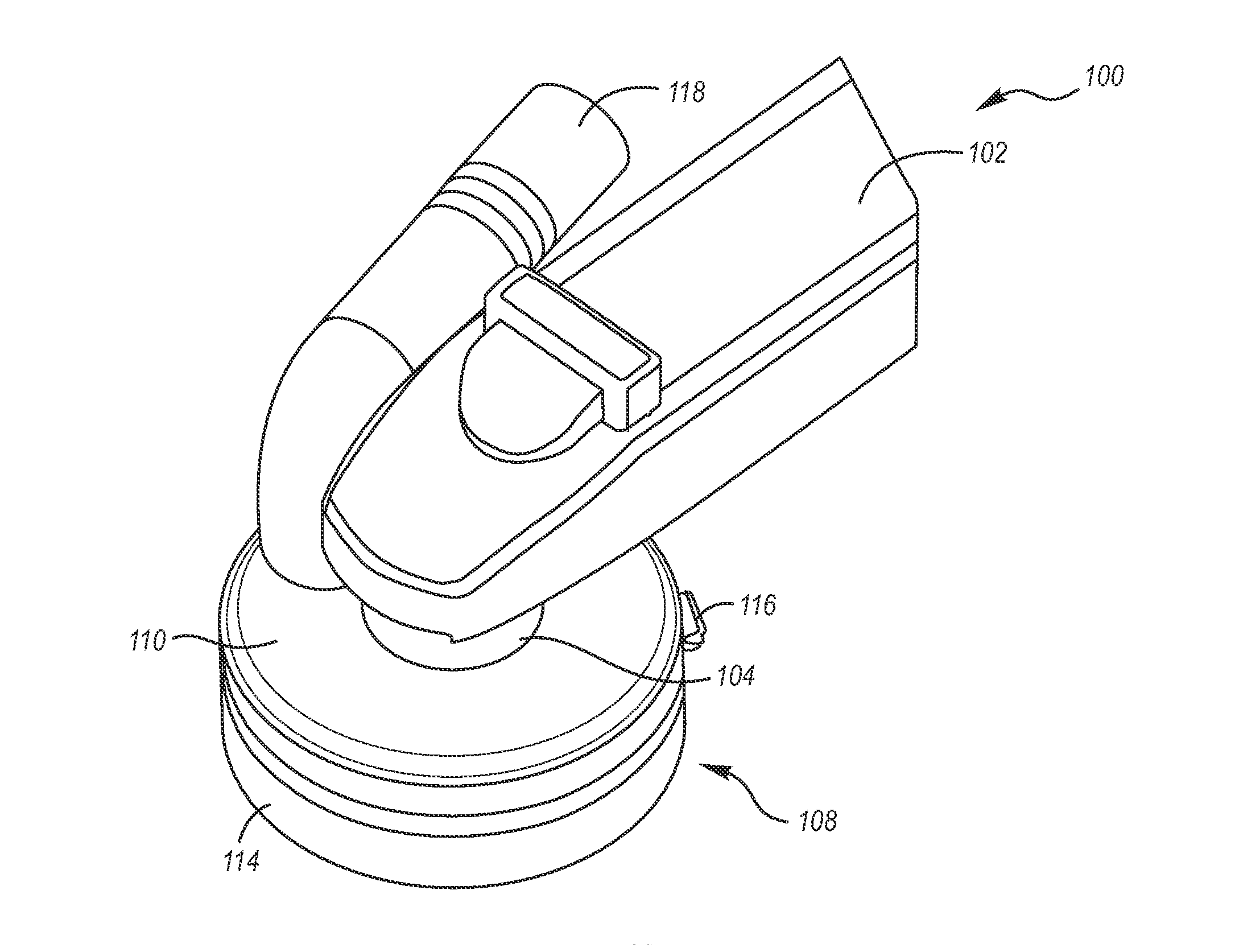
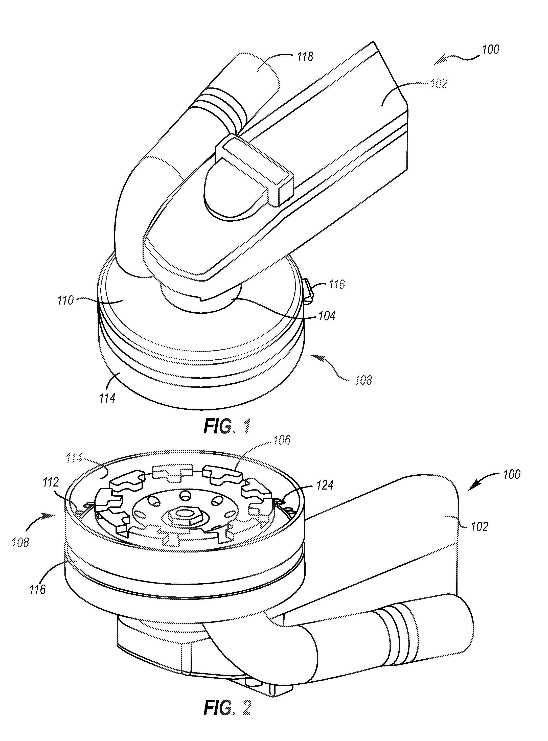
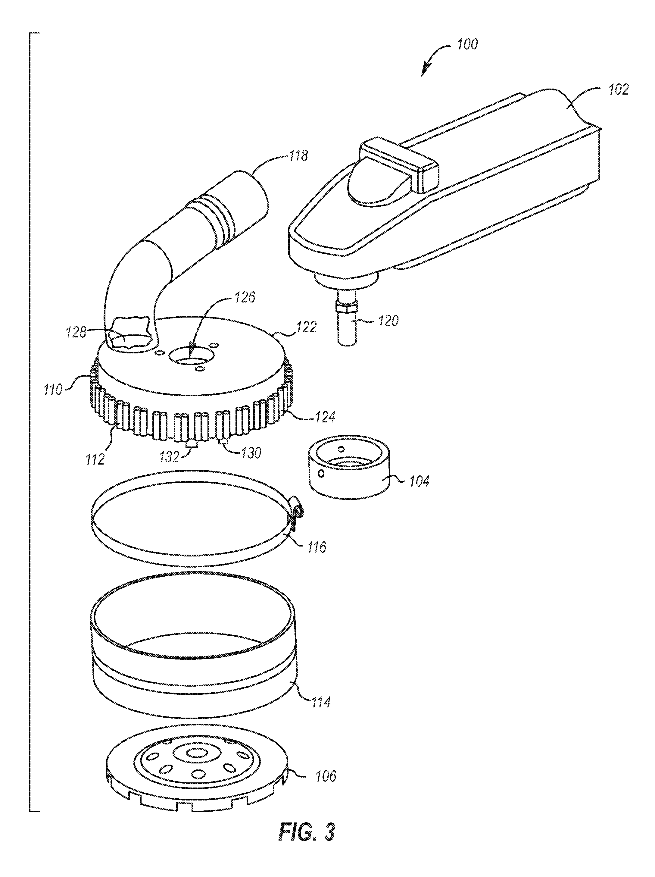
The invention is a shield for capturing dust created from a work surface by a rotary tool attachment. The shield has a shroud with air inlets and a flexible skirt that extends downward from the shroud to contact the work surface. The shield can be used with various types of rotary tools and vacuum sources. The invention is not limited to the specific structure and acts described in the preferred embodiments, but also includes any and all structures, materials, or acts that perform the same function.

Problems solved by technology

The removal of flooring tile is a dirty and time-consuming process.
However, this process usually results in a large amount of dust and debris that is ejected into the ambient air.
In turn, this requires a substantial amount of preparation time to protect surrounding areas from being contaminated with dust.
Additionally, the health of individuals in those areas may be negatively affected by the dust.
Furthermore, environmental regulations may prohibit the escape of the removed dust into the atmosphere.
However, there are significant drawbacks with these designs.
First, the location of the vacuum attachment may not be positioned to maximize the capture of the dust.
Second, the tube that couples the vacuum to the housing does not allow the tool to reach certain places, such as in corners and underneath cabinets.
Third, the durability of many products on the market is suspect.
Fourth, the cylindrical shape of the housing does not allow for the rotary tool attachment to reach against walls.
Fifth, the products may clog with pieces of debris or may strain the vacuum motors, which reduces the useable life of the vacuum.

Method used


Image

  • System and method for capturing dust created by rotary tool attachments
  • System and method for capturing dust created by rotary tool attachments
  • System and method for capturing dust created by rotary tool attachments

Examples


Embodiment Construction

[0026]The following detailed description is merely illustrative in nature and is not intended to limit the embodiments of the subject matter or the application and uses of such embodiments. Any implementation described herein as exemplary is not necessarily to be construed as preferred or advantageous over other implementations. Furthermore, there is no intention to be bound by any expressed or implied theory presented in the preceding technical field, background, brief summary, or the following detailed description.

[0027]The following description may refer to elements or features being “coupled” together. Although the drawings may depict one exemplary arrangement of elements, additional intervening elements, devices, features, or components may be present in an embodiment of the depicted subject matter. In addition, certain terminology may also be used in the following description for the purpose of reference only, and thus are not intended to be limiting. Furthermore, it should be...


PUM

PropertyMeasurementUnit
Fractionaaaaaaaaaa
Fractionaaaaaaaaaa
Lengthaaaaaaaaaa

Abstract

A system and method are provided for capturing dust created from a work surface by a rotary tool attachment. A shield is comprised of a ridged shroud and a flexible skirt. The shroud is configured to be coupled to a rotary tool, and to either fully enclose or partially expose the rotary tool attachment. The shroud has a plurality of air inlets, a first opening, and a second opening through the top surface of the shroud. The first opening receives a mechanical driveshaft of the rotary tool and the second opening is coupled to an external vacuum source. The flexible skirt is coupled to a perimeter of the shroud and extends downward from above the top surface of the shroud and is configured to contact the work surface.

Description

CROSS-REFERENCE TO RELATED APPLICATIONS[0001]This application is a continuation-in-part of and claims priority to U.S. patent application Ser. No. 13 / 086,334, titled “System and method for capturing resultant dust from power tool operation,” and filed on Apr. 13, 2011 by Jack M. King, Jr.; U.S. patent application Ser. No. 13 / 309,037, titled, “Vacuum device for capturing dust within a receptacle,” filed on Dec. 1, 2011 by Jack M. King, Jr.; U.S. patent application Ser. No. 13 / 691,408, titled, “System and method for capturing dust from power tool operation,” filed on Nov. 30, 2012 by Jack M. King, Jr. and U.S. patent application Ser. No. 13 / 691,461, titled, “System and Method for Capturing Dust from Debris Transportation,” filed on Nov. 30, 2012 by Jack M. King, Jr. The contents of the above mentioned applications are hereby incorporated by reference.TECHNICAL FIELD[0002]Embodiments of the subject matter described herein relate generally to power tool accessories. More particularly, e...

Claims


Application Information

Patent Timeline
IPC IPC(8): A47L9/02
CPCA47L9/02Y10T29/49947B24B55/102B23Q11/0046
Inventor KING, JR., JACK M
Owner SKITTER & SQUIRT ADVENTURES
Learn More