Deployable radiator having an increased view factor

a technology of view factor and deployable radiator, which is applied in the direction of cosmonautic thermal protection, transportation and packaging, cosmonautic vehicles, etc., can solve the problems of reducing the thermal rejection capacity of deployable radiators, complicating the design of deployable radiators and its internal heat pipe arrangement, and improving the thermal rejection capability of deployable radiators. , the effect of simple internal heat pipe arrangemen

Active Publication Date: 2013-08-08
LOCKHEED MARTIN CORP
View PDF1 Cites 22 Cited by
  • Summary
  • Abstract
  • Description
  • Claims
  • Application Information

AI Technical Summary

Benefits of technology

[0009]Various aspects of the subject technology provide a deployable radiator arrangement for GEO spacecraft in which the deployable radiators are stowed on the east and west panels of the spacecraft. This arrangement allows the deployable radiators to be deployed without interfering with solar arrays and communication antennas and without the need to incorporate cutouts in the deployable radiators, thereby improving the thermal rejection capabilities of the deployable radiators. Because clearance cutouts are not needed, the design of the deployable radiators and their respective internal heat pipe arrangement is less complicated. As a result, the deployable radiators may have a rectangular shape with a simple internal heat pipe arrangement and high radiator efficiency. The simple internal heat pipe arrangement may follow a general path within the deployable radiators without the need to accommodate clearance cutouts. In addition, the manufacture of the deployable radiators is more economical than deployable radiators used in conventional GEO spacecraft.
[0010]In addition, the deployable radiators may be positioned at an angle past the plane of the fixed north and south radiators, in other words the deployable radiator is positioned at an angle that exceeds 90 degrees. For certain aspects of spacecraft configurations, the view factor of the radiator backside to deep space is improved by positioning the radiator at an angle that exceeds 90 degrees, thereby improving the efficiency of the thermal control system.

Problems solved by technology

A drawback of this arrangement is that the deployable radiators must fit underneath the stowed solar array in the stowed position.
The clearance cutouts decrease the thermal rejection capacity of the deployable radiators.
In addition, the clearance cutouts complicate the design of the deployable radiators and its internal heat pipe arrangement.
This deployment arrangement is more complicated, has greater potential for undesirable interferences, and is more costly to implement.

Method used


Image

  • Deployable radiator having an increased view factor
  • Deployable radiator having an increased view factor
  • Deployable radiator having an increased view factor

Examples


Embodiment Construction

[0027]In the following detailed description, numerous specific details are set forth to provide a full understanding of the subject technology. It will be apparent, however, to one ordinarily skilled in the art that the subject technology may be practiced without some of these specific details. In other instances, well-known structures and techniques have not been shown in detail so as not to obscure the subject technology. Like components are labeled with identical element numbers for ease of understanding.

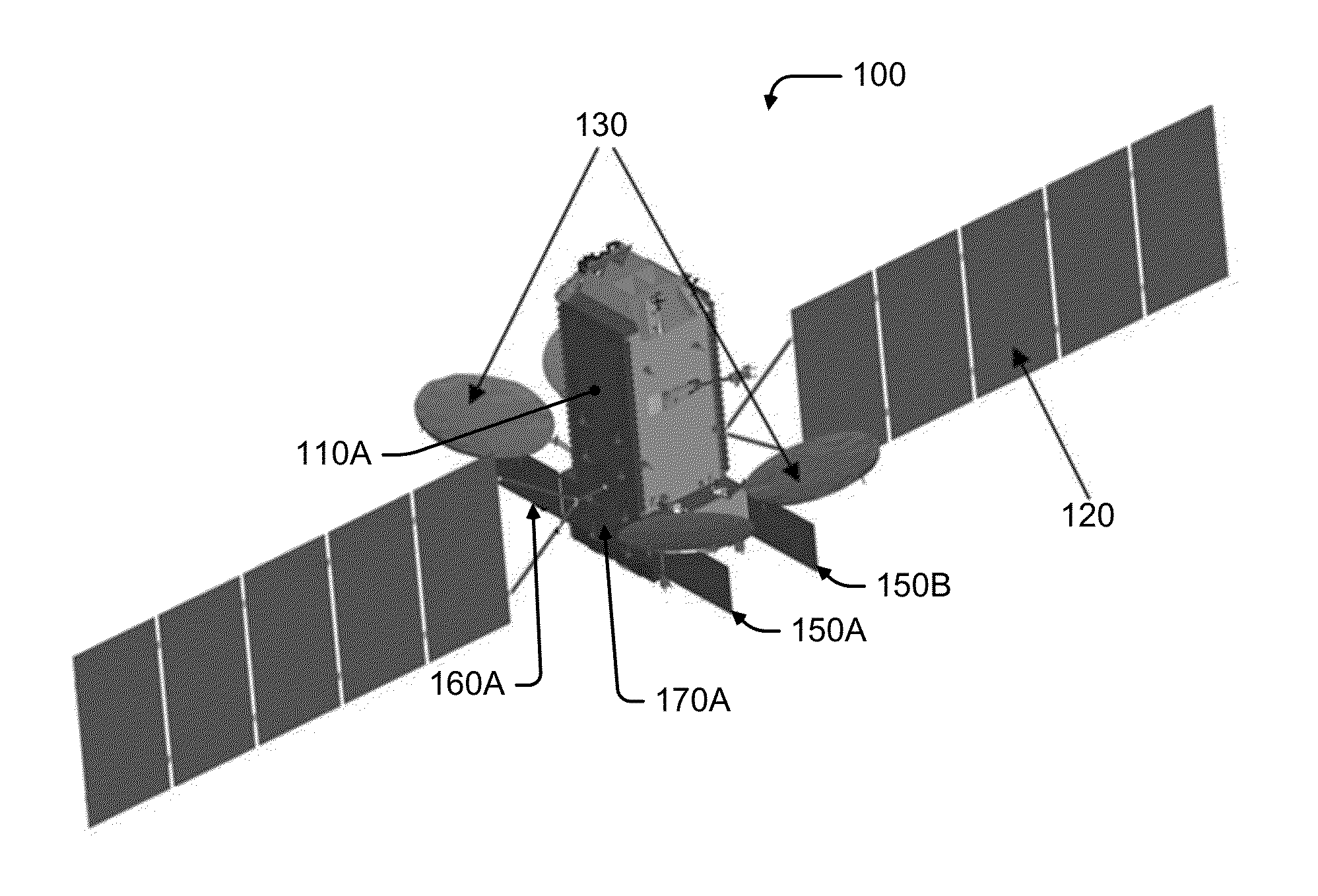
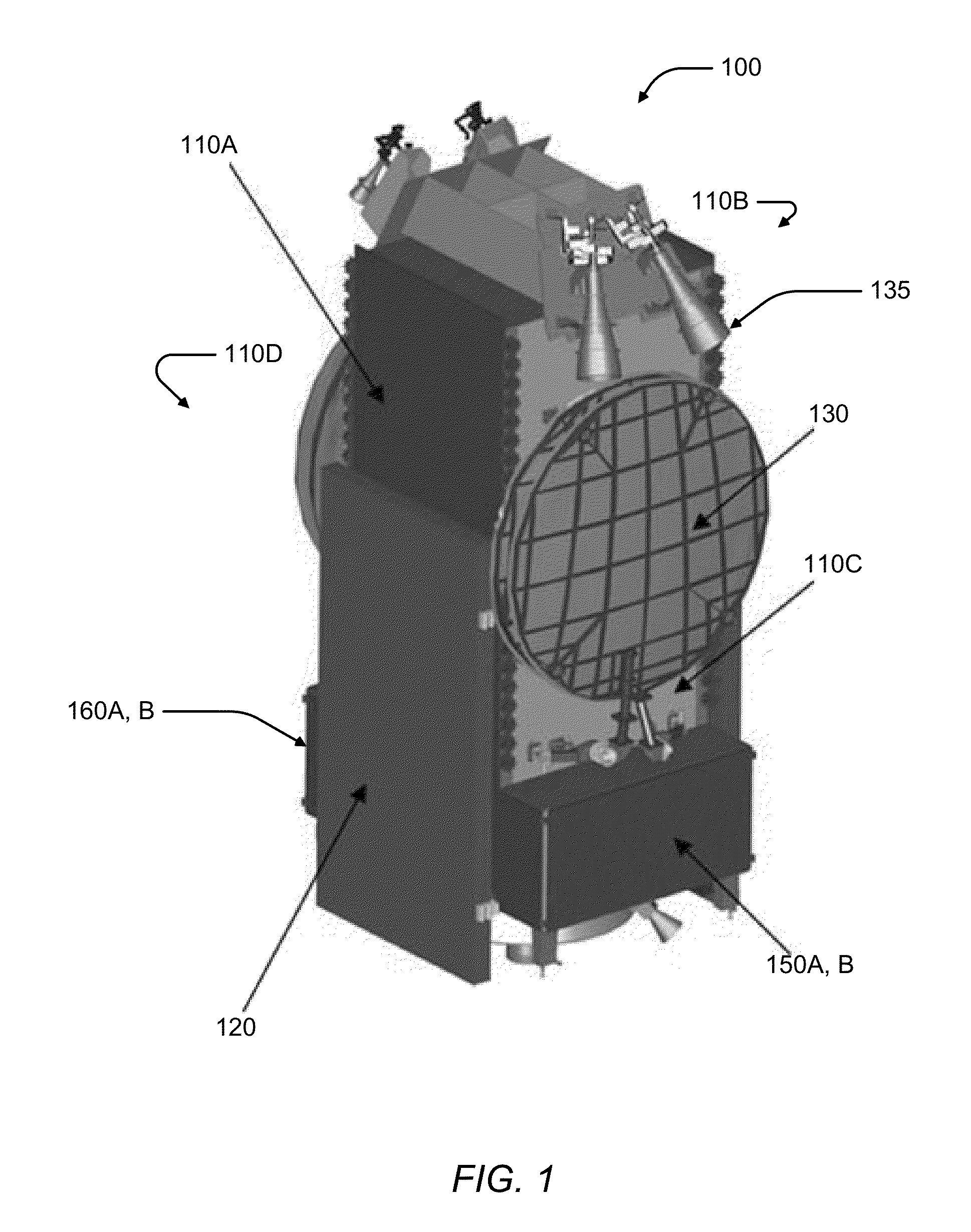
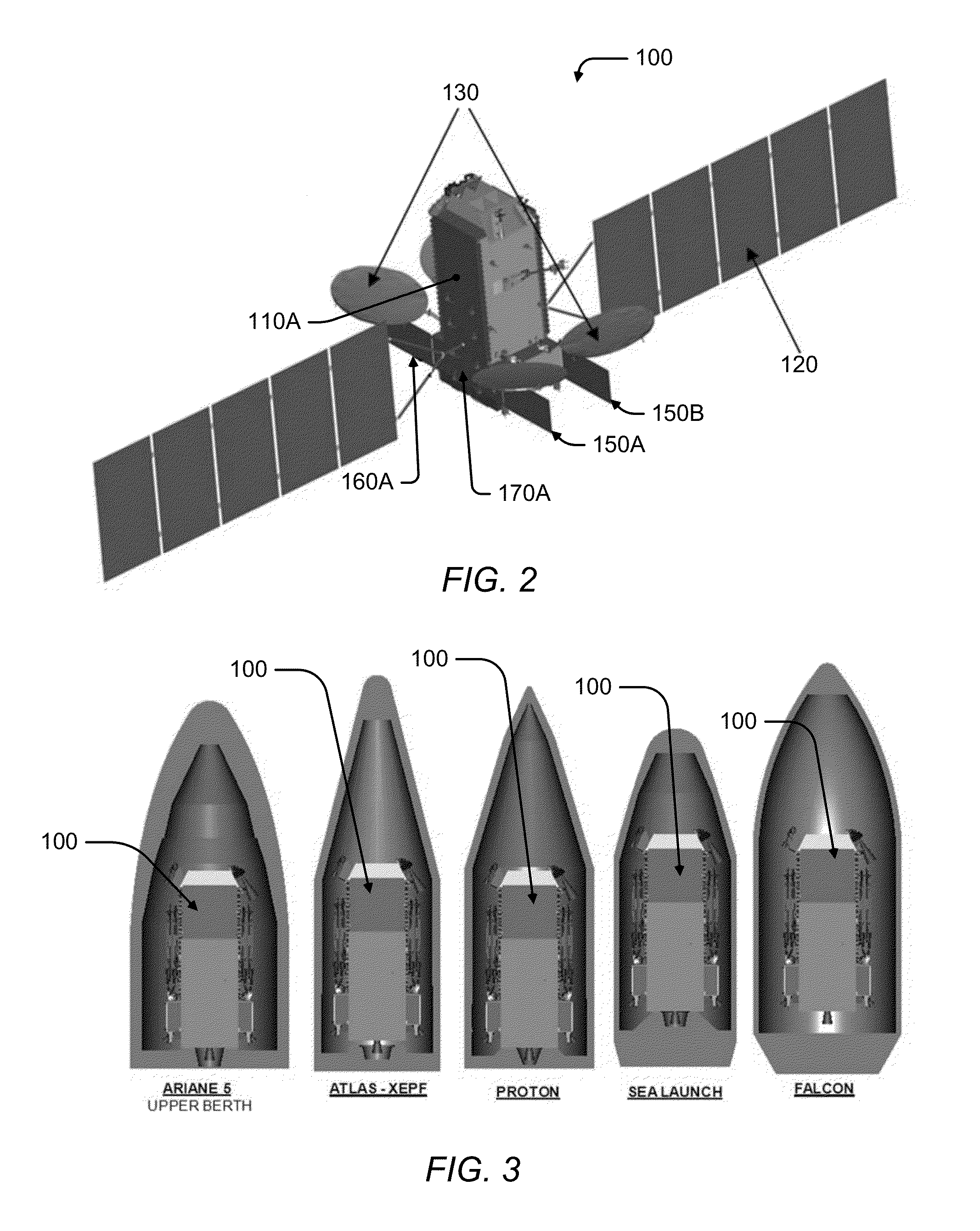
[0028]Various aspects of the subject technology provide a method for cooling a GEO spacecraft without interfering with solar arrays and communication antennas, thereby increasing the thermal rejection capabilities of the deployable radiators by minimizing clearance cutouts. In one aspect, the design of the deployable radiators and their respective internal heat pipe arrangement is less complicated, and therefore more economical, than conventional GEO spacecraft.

[0029]FIG. 1 illus...


PUM

PropertyMeasurementUnit
angleaaaaaaaaaa
angleaaaaaaaaaa
angleaaaaaaaaaa

Abstract

A geostationary earth orbit (GEO) spacecraft is disclosed that includes a body with north, east, south, and west sides and a north-south axis. The spacecraft has at least one deployable radiator rotatably coupled to the body. The deployable radiator has a stowed position proximate to one of the east and west sides and a deployed position that is greater than 90 degrees from the north-south axis in a direction away from the respective one of the east and west sides.

Description

CROSS-REFERENCE TO RELATED APPLICATIONS[0001]This application is a Continuation-in-Part of application Ser. No. 13 / 368,304 filed on Feb. 7, 2012, which is hereby incorporated in its entirety by reference.STATEMENT REGARDING FEDERALLY SPONSORED RESEARCH OR DEVELOPMENT[0002]Not Applicable.BACKGROUND[0003]1. Field[0004]The present invention generally relates to Geostationary Earth Orbit (GEO) spacecraft and, in particular, relates to a non-interfering deployable radiator arrangement for GEO spacecraft.[0005]2. Description of the Related Art[0006]Conventionally, a GEO communications spacecraft may have deployable radiators that are stowed against the north or south spacecraft panels underneath the stowed solar arrays. The rationale for this is that the north or south panels of the spacecraft generally have the largest surface area and minimize interference with communications antennas that are mounted on the east and west sides of the spacecraft. Once in orbit and after the solar arrays...

Claims


Application Information

Patent Timeline
Patent Type & Authority Applications(United States)
IPC IPC(8): B64G1/58B23P15/26
CPCB64G1/58B23P15/26B64G1/222Y10T29/4935B64G1/503B64G1/506B64G1/641B64G1/44
Inventor GOODZEIT, NEIL E.WONG, HAMILTONHENTOSH, DAVID J.
Owner LOCKHEED MARTIN CORP
Why Eureka
Try Eureka