
Tile, assembly of tiles with a carrier, method of manufacturing an assembly

Inactive Publication Date: 2013-08-08
NEDERLANDSE ORG VOOR TOEGEPAST-NATUURWETENSCHAPPELIJK ONDERZOEK (TNO)
View PDF7 Cites 23 Cited by
  • Summary
  • Abstract
  • Description
  • Claims
  • Application Information

AI Technical Summary

Benefits of technology

The methods described in this patent make it easy to attach tiles to a carrier without limiting the carrier's movement. The tiles can be aligned with the carrier by using magnetic poles, and they can also be connected to the carrier using conductive wires. This allows for a reliable attachment and efficient electrical conduction. The tiles can also be overlapping, so that the carrier's surface is fully covered even if it is stretched.

Problems solved by technology

Although this allows certain degrees of freedom it is still not possible to deform such devices into arbitrary shapes, for example in the form of a spherical shape.
However, the resulting product can not be deformed into another shape for other applications, let alone that the product is arbitrarily deformable during use.

Method used


Image

  • Tile, assembly of tiles with a carrier, method of manufacturing an assembly
  • Tile, assembly of tiles with a carrier, method of manufacturing an assembly
  • Tile, assembly of tiles with a carrier, method of manufacturing an assembly

Examples


Embodiment Construction

[0041]The invention is described more fully hereinafter with reference to the accompanying drawings, in which embodiments of the invention are shown. This invention may, however, be embodied in many different forms and should not be construed as limited to the embodiments set forth herein. Rather, these embodiments are provided so that this disclosure will be thorough and complete, and will fully convey the scope of the invention to those skilled in the art. In the drawings, the size and relative sizes of layers and regions may be exaggerated for clarity.

[0042]It will be understood that, although the terms first, second, third etc. may be used herein to describe various items these items should not be limited by these terms. Items are understood too mean features described such components or elements or aspects of components or elements, e.g. a surface of an element or a height of an element. These terms are only used to distinguish one item from another item. Thus, a first item cou...


PUM

PropertyMeasurementUnit
Fractionaaaaaaaaaa
Electrical conductivityaaaaaaaaaa
Electrical conductoraaaaaaaaaa

Abstract

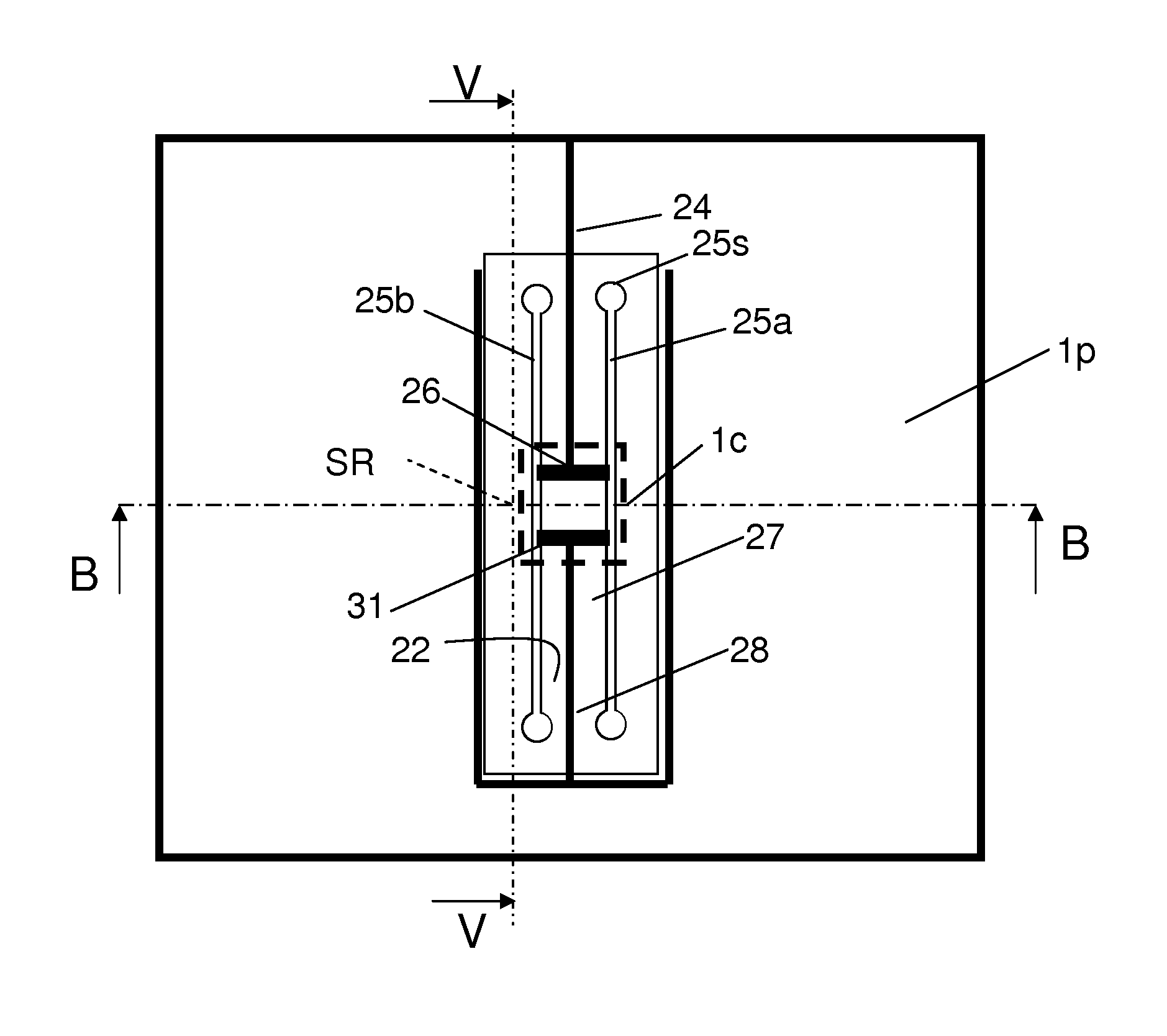
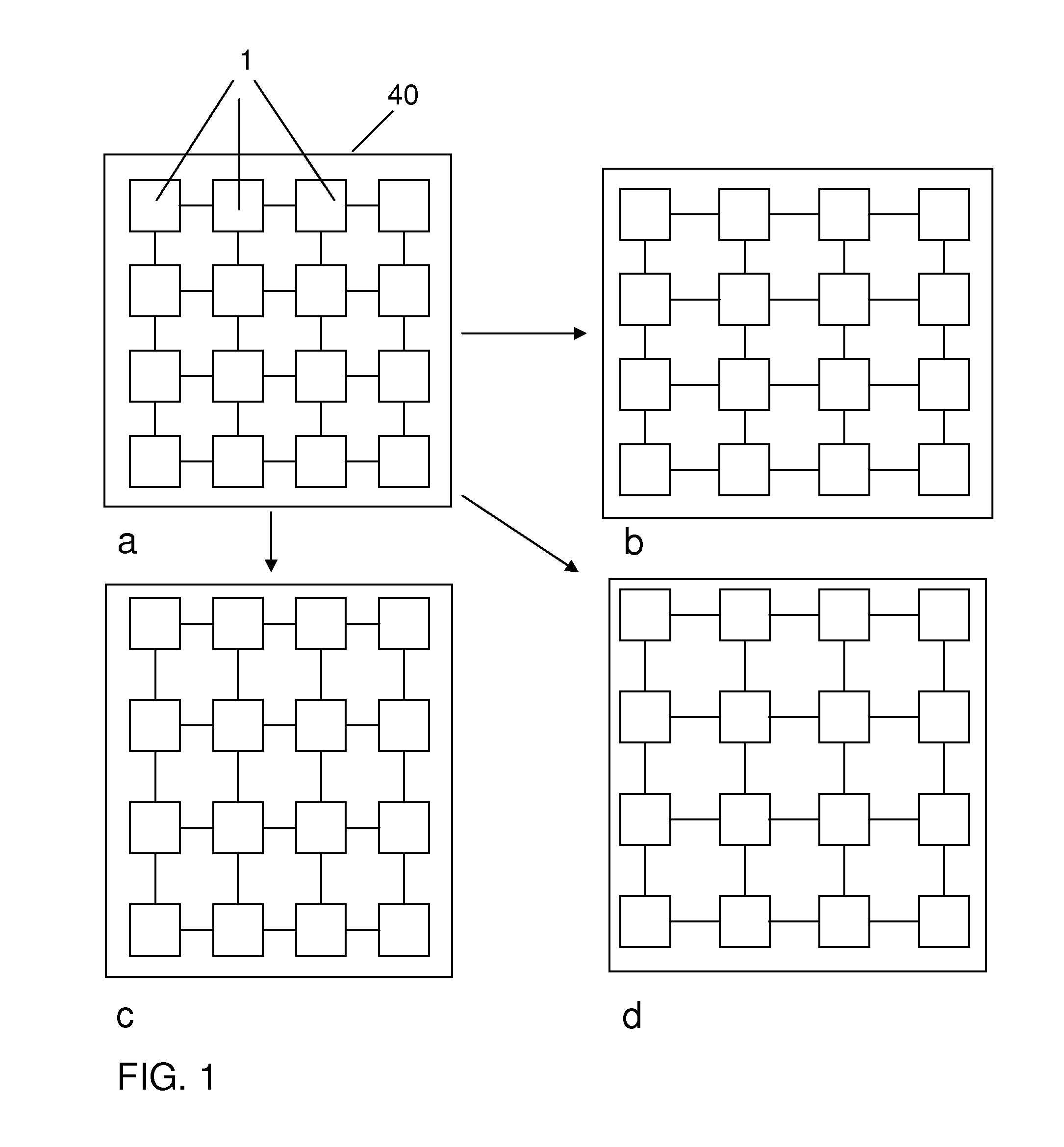
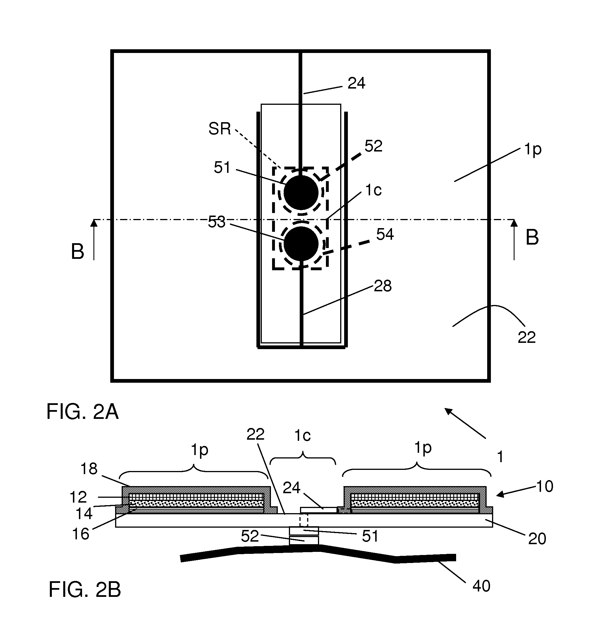
An assembly of a plurality of tiles (1) with a carrier (40). The tiles (1) comprise a foil (20) with an electro-physical transducer (10) and electrical connectors (24, 28) to said transducer. The tiles are mechanically and electrically coupled to the carrier in a connection portion (1c) of said tiles.

Description

BACKGROUND OF THE INVENTION[0001]1. Field of the Invention[0002]The present invention relates to a tile, in particular a tile comprising an electro-physical transducer.[0003]The present invention further relates to an assembly of tiles with a carrier.[0004]The present invention further relates to a method of manufacturing an assembly.[0005]2. Related Art[0006]An electro-physical transducer is defined herein as a device that converts an electrical signal into a physical phenomenon, or that converts a physical phenomenon into an electrical signal. Examples of the first are electro-luminescent devices, electro-acoustic devices, and electro-chrome devices. Examples of the second are photovoltaic devices, acoustic sensors, and touch sensors.[0007]Electro-optical devices are known that are manufactured in the form of a flexible foil. Although this allows certain degrees of freedom it is still not possible to deform such devices into arbitrary shapes, for example in the form of a spherical...

Claims


Application Information

Patent Timeline
IPC IPC(8): H05K1/02H05K13/04H02S30/20H05B44/00
CPCG09F9/00Y10T29/4913H01L27/3293H01L51/5203H01L2251/5338H01L2251/5361H01R4/04H01R4/70H01R12/7076H05K1/0283H05K1/038H05K1/147H05K1/189H05K3/321H05K3/325H05K3/365H05K2201/029H05K2201/0311H05K2201/046H05K2201/083H05K2201/09081H05K2201/09281H05K2201/10106H05K2201/10287H05K2201/10484H05B33/0896H05B33/10H05K1/0277H05K13/04Y02E10/50H01L31/0392H01L31/042G09F19/22H10K59/18H10K2102/311H05B45/60H10K50/805
Inventor VAN DEN BRAND, JEROENVAN HECK, GERARDUS TITUSDE KOK, MARGARETHA MARIA
Owner NEDERLANDSE ORG VOOR TOEGEPAST-NATUURWETENSCHAPPELIJK ONDERZOEK (TNO)
Learn More