Method and a device for monitoring an engine

a technology for monitoring engines and aircraft, applied in the direction of engine fuction, analog and hybrid computing, registering/indicating, etc., can solve the problems of limited life of parts, a certain number of wear cycles, and one hour of flying, so as to reduce the involvement of pilots

Active Publication Date: 2013-08-08
EUROCOPTER
View PDF2 Cites 1 Cited by
  • Summary
  • Abstract
  • Description
  • Claims
  • Application Information

AI Technical Summary

Benefits of technology

[0046]An object of the present invention is thus to provide a method of monitoring an engine having limited-lifetime parts, the method seeking at least to minimize the involvement of a pilot in the monitoring.

Problems solved by technology

Nevertheless, each engine usually includes parts that are of limited lifetime.
Depending on the utilization conditions of the aircraft, one hour of flying then gives rise to a certain number of wear cycles that may vary from one limited-lifetime part to another.

Method used


Image

  • Method and a device for monitoring an engine
  • Method and a device for monitoring an engine

Examples


Embodiment Construction

[0104]Elements present in more than one of the figures are given the same references in each of them.

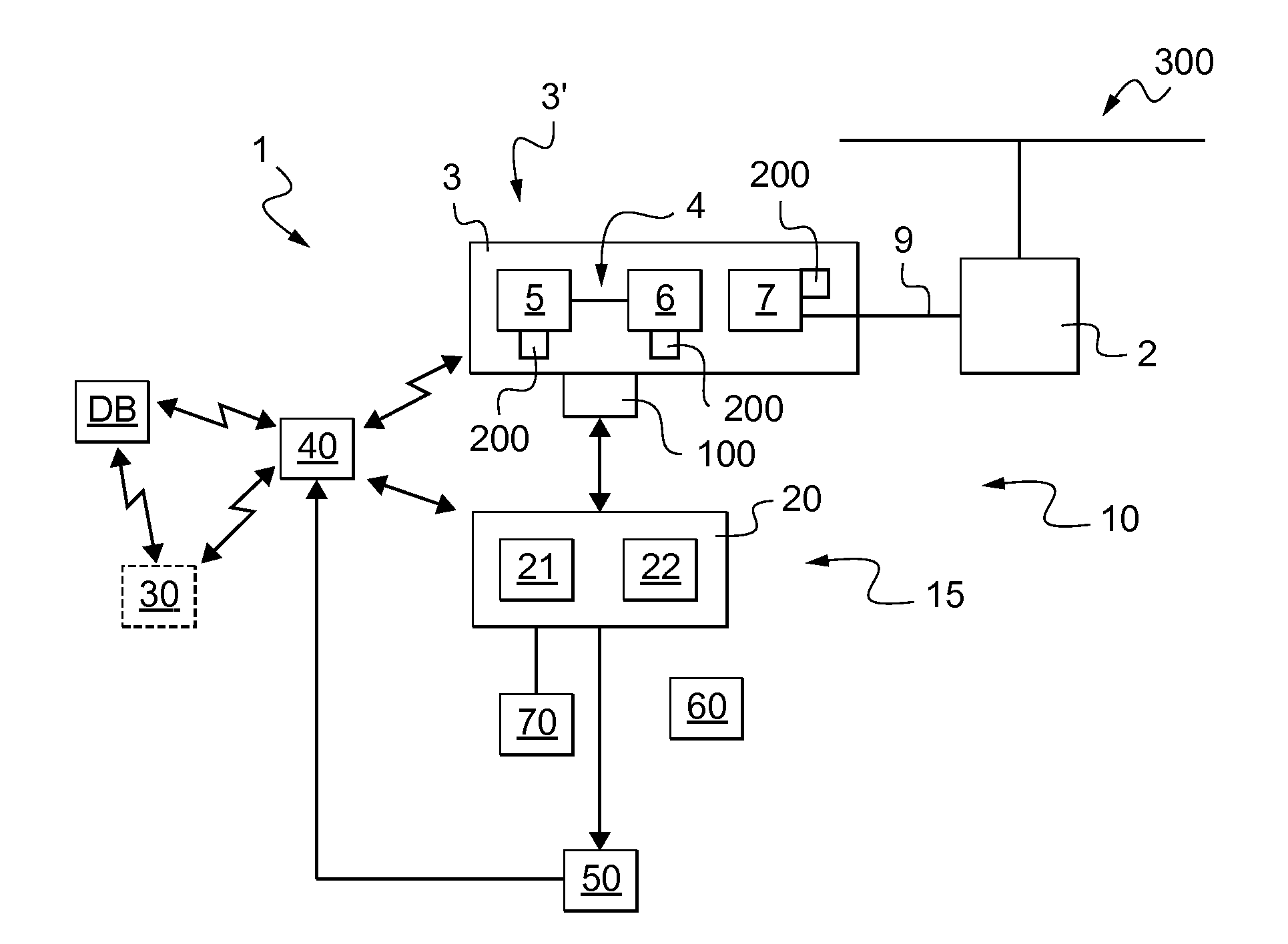
[0105]FIG. 1 shows an aircraft 1 having a rotary wing 300.

[0106]The aircraft 1 has a power plant 3′. The power plant 3′ includes at least one turbine engine 3 for driving the rotary wing 300 via a main power transmission gearbox (MGB) 2.

[0107]Each engine comprises a turboshaft engine having a gas generator 4 and a free turbine 7. For example, the gas generator comprises a compressor 5 co-operating with a high-pressure turbine 6 that is arranged upstream from the free turbine 7.

[0108]The free turbine 7 may then be connected to the main power transmission gearbox (MGB) 2 via a drive train 9. By way of example, the drive train 9 has an outlet shaft that is driven in rotation by the free turbine.

[0109]The aircraft 1 also includes a monitoring device 10 for monitoring those parts of an engine that have a limited lifetime, and more precisely for monitoring parts of the turbine engine 3. By...


PUM


Abstract

A method of monitoring at least one limited-lifetime part. During an identification step (STP1), storage means (40) store a list including a reference for each limited-lifetime part of an engine (3). During an information-search step (STP2), the storage means (40) communicate with a centralized data system (DB) in order to store for each identified part the corresponding maintenance data. During a monitoring step (STP3), the wear of the engine is monitored by using the information stored in the storage means (40).

Description

CROSS REFERENCE TO RELATED APPLICATIONS[0001]The present application claims priority to French patent application No. FR 12 / 00377 filed on Feb. 8, 2012, the content of which is incorporated in its entirety by reference herein.BACKGROUND OF THE INVENTION[0002](1) Field of the Invention[0003]The present invention relates to a method of monitoring an engine, and also to the associated device.[0004](2) Description of Related Art[0005]More particularly, the invention lies in the technical field of maintaining an engine of an aircraft, and in particular of a rotary-wing aircraft.[0006]Conventionally, a rotary-wing aircraft has a main rotor providing the aircraft with lift and possibly also with propulsion. The main rotor is driven in rotation by at least one engine.[0007]For example, at least one turboshaft engine drives a main power transmission gearbox (MGB), and the MGB drives the main rotor in rotation.[0008]Each engine is then controlled by a respective engine computer that possibly ...

Claims


Application Information

Patent Timeline
Patent Type & Authority Applications(United States)
IPC IPC(8): G06F17/00
CPCG06F17/00F05D2260/821F05D2270/44F01D19/00F01D21/003G07C5/006G07C5/085F05D2260/80F05D2260/81F05D2260/83G07C5/008
Inventor VIEIRA, HILARIO
Owner EUROCOPTER
Why Eureka
Try Eureka