
Technology for simulating and/or controlling communication optical networks

Active Publication Date: 2012-01-05
ECE TELECOM LTD
View PDF4 Cites 2 Cited by
  • Summary
  • Abstract
  • Description
  • Claims
  • Application Information

AI Technical Summary

Benefits of technology

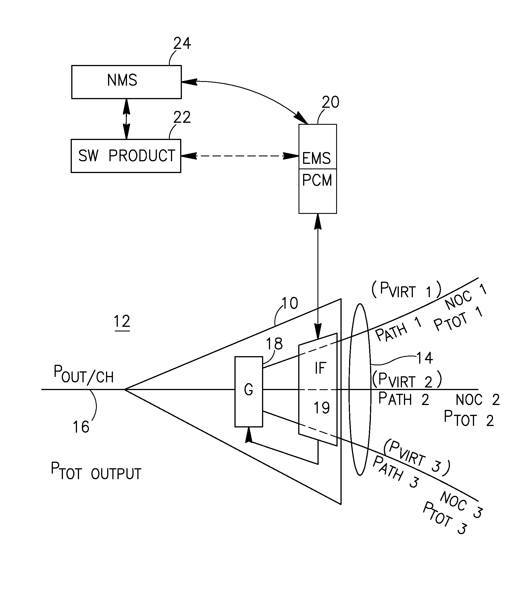
[0025]Moreover, it has been proven that the output power per channel will remain at a pre-selected optimal desired level Pout,desired even when real parameters (number of channels NOC, etc) of the incoming paths change during operation. In other words, the routes / paths being estimated and powered according to the proposed method will be independent from one another and will practically not affect the output power per channel. By using Pvirtual instead of Ptot, the amplifier becomes properly designed and properly controlled for every path capacity that does not exceed a planned number of channels (considered the maximally possible for the path).
[0042]3. Allows taking into account spectral distribution and channels types for every path by introducing a weight function. The weight function allows an operator / user to emphasize the paths according to their properties and the required path's quality of service.
[0043]4. Allows high level of automation at the simulation level, with saving the running time and minimized involvement of human resources.
[0044]5. As a result of the simulation, the information required for the power control and traffic provisioning becomes available. For example, using the proposed Pvirt and the calculated input signal parameters allows obtaining Gain value of the node, Pout / channel per path, and Ptot output, OSNR output per path and per channel.
[0045]6. Allows performing such power control of optical nodes (say, amplifiers), which ensures maintaining the desired output power per channel, and reaching independence of paths in the network.

Problems solved by technology

In the process of designing / simulating a network, optical amplifiers, as well as OADMs and switches, are network nodes which are most problematic.
The main difficulty, due to the dynamic character of the network, is setting the correct working point for any specific optical node (amplifier or other) without knowing exact number of channels to be handled / amplified, and without knowing the channel allocation of the handled signal.

Method used


Image

  • Technology for simulating and/or controlling communication optical networks
  • Technology for simulating and/or controlling communication optical networks
  • Technology for simulating and/or controlling communication optical networks

Examples


Embodiment Construction

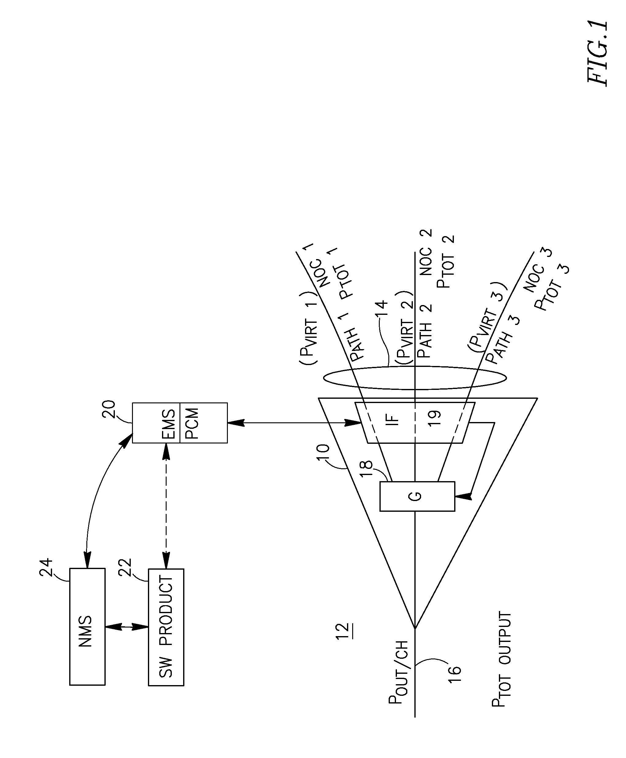
[0054]FIG. 1 shows an optical amplifier 10 being a node in an optical mesh network 12. Actually, instead of the amplifier there may be another network element (OADM, switch) controlled by EMS 20 to perform power control. The amplifier 10 is connected to an input optical fiber schematically shown as 14, and to an output optical fiber schematically shown as 16. The amplifier's gain is schematically shown as a box G marked 18. Let a network designer has information that the amplifier 10 is expected to receive maximum three communication paths (Path 1, Path 2 and Path 3), and these paths will probably have the following capacity: they will comprise no more than the number of optical channels NOC1, NOC2, NOC3, respectively. Let, in the ideal case, the amplifier 10 should amplify any of the received optical channels so as to provide a desired total output power Pout total. It is selected in advance, and is usually the maximal possible value as understood to those skilled in the art.

[0055]...


PUM


Abstract

A technique for controlling power of a network node in an optical mesh network, comprising: determining a number of optical paths ingressing or expected to ingress the node, determining capacity or expected capacity of each of the paths; calculating for each of the paths a virtual input power Pvirtual, based on estimation of relative capacity of a specific path with respect to total capacity of all the paths; applying to the network node a power control mechanism, while utilizing a corresponding virtual input power Pvirtual as input power of any of the paths.

Description

FIELD OF THE INVENTION[0001]The present invention relates to a technique for designing, constructing and / or simulating operation of communication optical networks, especially mesh networks and those which are expected to change with time due to new requirements.BACKGROUND OF THE INVENTION[0002]The main problem of all existing methods for designing or simulating a dynamic cross-connecting (XC) network is inability to provide a well-based, highly probable traffic matrix (i.e., a traffic prediction table for the network), which is usually unavailable at a design stage, and even at a given state of a real existing network.[0003]The detailed traffic planning is usually impossible, and indeed—would such be possible, new methods for planning / designing / simulation would not be required.[0004]U.S. Pat. No. 7,330,652B describes a technique for selecting optical amplifier placement in an optical network. In one embodiment an algorithm is used to eliminate from consideration optical amplifier co...

Claims


Application Information

Patent Timeline
IPC IPC(8): H04J14/00
CPCH04J14/0221H04Q2011/0079H04Q11/0062H04J14/0284
Inventor GUTIN, MICHAELVELDER, ALEXANDERTOURGEMAN, LIOR
Owner ECE TELECOM LTD
Learn More