Pneumatic tire tread comprising a plurality of incisions

a pneumatic tire and plurality of incisions technology, applied in the field of pneumatic tire treads, can solve the problems of energy loss, energy loss through hysteresis, energy loss, etc., and achieve the effect of ensuring the closure of said sipes and limiting the deformation of the blocks

Inactive Publication Date: 2013-08-15
MICHELIN & CO CIE GEN DES ESTAB MICHELIN +1
View PDF3 Cites 30 Cited by
  • Summary
  • Abstract
  • Description
  • Claims
  • Application Information

AI Technical Summary

Benefits of technology

[0050]By inclining the sipes in the depth of the tread, better closure of said sipes can be ensured. The deformation of the blocks is thus limited even further.

Problems solved by technology

These energy losses are also dependent on the deformation cycles experienced by the tread as the tire is driven on.
Under the action of these various forces, the tread deforms, leading to energy losses through hysteresis.
This deformation of the lateral walls leads to energy losses through hysteresis.
The fact that such a small radius of curvature exists leads to a high degree of flexing of the circumferential band ahead of the contact patch.
This high degree of flexing has a tendency to part the lateral walls of the adjacent blocks and therefore to widen the sipes just before they enter the contact patch, the result of this being to increase hysteresis energy losses.
Thanks to the chamfers, hysteresis energy losses are limited still further.
Hysteresis energy losses are limited even further.
Beyond 45 degrees, the area of contact with the ground and the rigidity of the blocks is reduced excessively and this can ultimately impair the correct operation of the tread.
These non-directional tires do not have a preferred direction of running.
Hysteresis energy losses are therefore limited even more.
The deformation of the blocks is thus limited even further.

Method used


Image

  • Pneumatic tire tread comprising a plurality of incisions
  • Pneumatic tire tread comprising a plurality of incisions
  • Pneumatic tire tread comprising a plurality of incisions

Examples


Embodiment Construction

[0061]In the description that follows, elements that are identical or similar will be denoted by identical references.

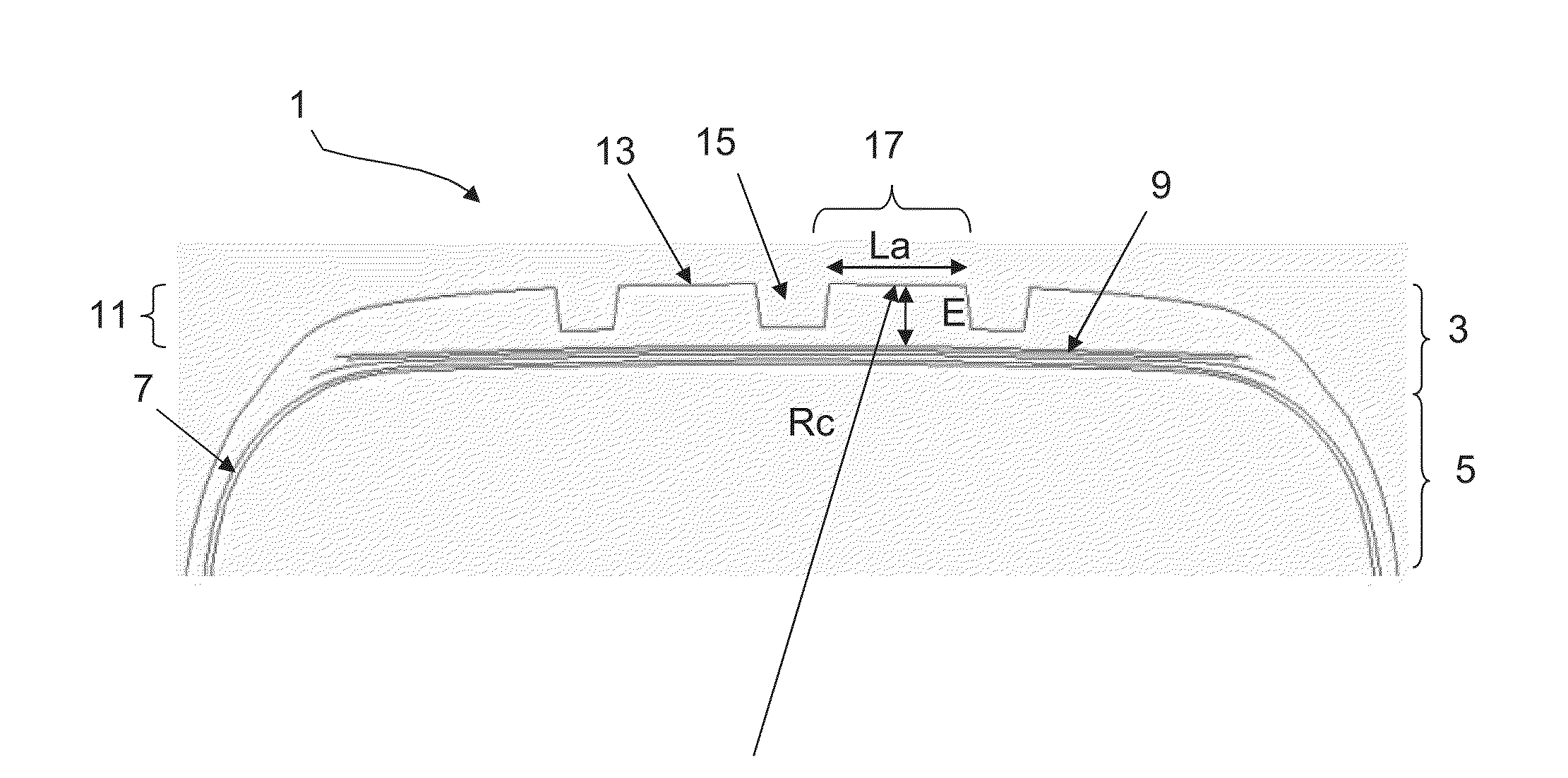
[0062]FIG. 1 schematically depicts a partial view in cross section of a tire 1.

[0063]The tire 1 comprises a crown comprising a crown region 3 extended laterally by sidewalls 5 connecting to beads (not depicted) intended to be in contact with a mounting rim.

[0064]The tire 1 comprises a carcass reinforcement 7 extending from one bead to the other bead via the sidewalls 5 and the crown region 3.

[0065]The crown region 3 comprises a reinforcement 9 surmounted radially on the outside by a tread 11.

[0066]The tread 11 comprises, radially on the outside, a tread surface 13 intended to come into contact with the ground when the vehicle is running.

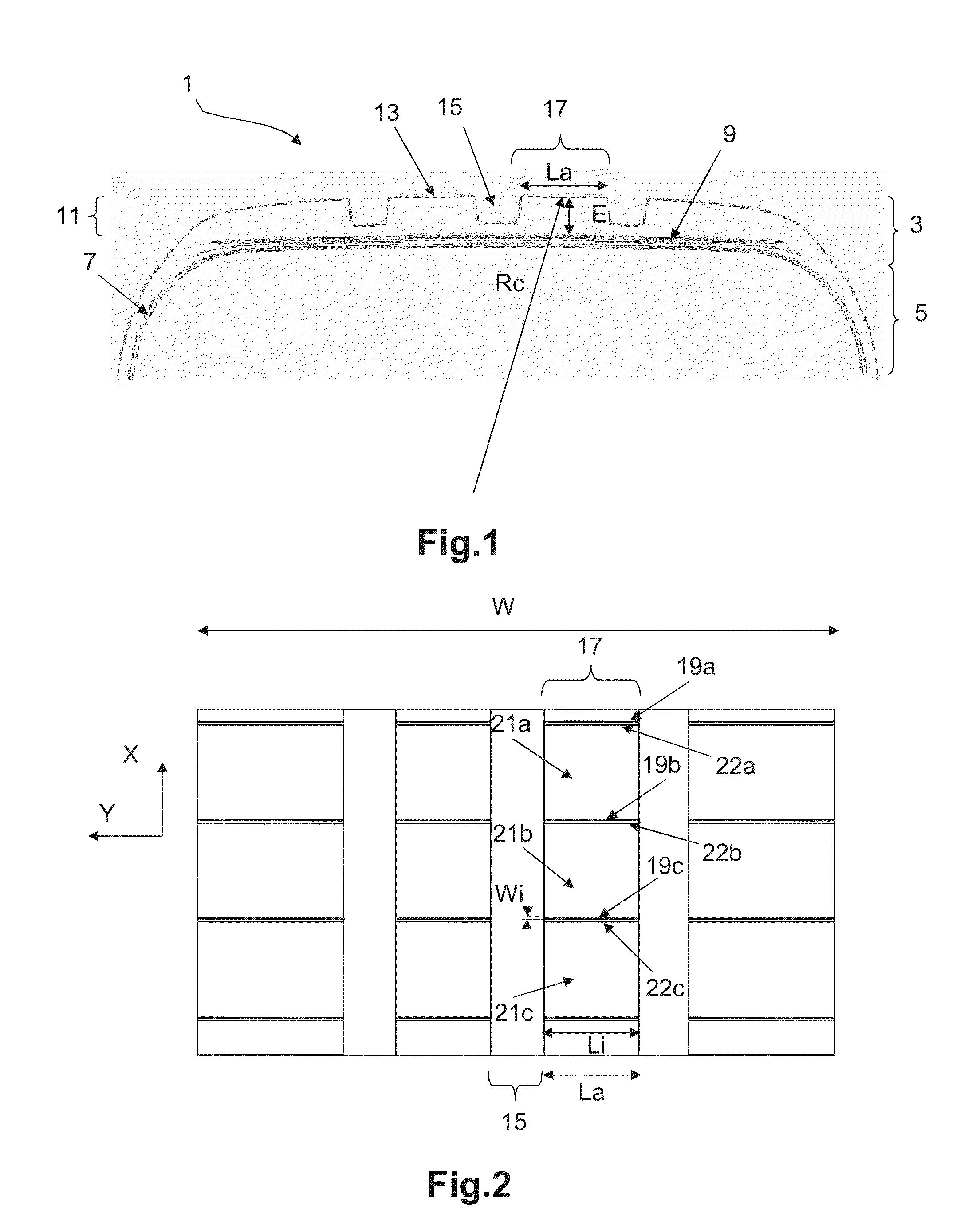
[0067]The tread 11 comprises a plurality of grooves 15.

[0068]The grooves 15 delimit raised circumferential bands 17.

[0069]Each circumferential band 17 has a contact surface intended to come into contact with the ground when the tire i...


PUM


Abstract

A tread comprises a central zone with a width of between 70% and 80% of the width W of the tread. The central zone comprises one or more circumferential bands, each being delimited by two grooves of a width greater than or equal to 2 mm, and each comprising a contact surface intended to come into contact with the ground and a plurality of transverse sipes distributed evenly in the circumferential direction. Each sipe has, on the contact surface, a width less than 2 mm so as to define a mean circumferential void ratio, which is between 0.5 times and 1.5 times the ratio between a mean thickness (E) of the circumferential band to a mean circumferential radius of curvature (Rc) of the said circumferential band. The sipes divide the circumferential band into a succession of blocks, each having two edge corners intersecting the contact surface of the circumferential band, at least one of the edge corners of said block extending radially by an inclined part forming a chamfer. This inclined part connects the edge corner to a lateral wall of the block so as to generate an offset in the circumferential direction between the said edge corner and the lateral wall of the block.

Description

BACKGROUND[0001]1. Field[0002]The present invention relates to a tire tread comprising a plurality of sipes and associated means for reducing the rolling energy consumption of this tread. The invention relates notably to treads for tires intended to be fitted to passenger motor vehicles.[0003]2. Description of Related Art[0004]Reducing the energy consumption associated with moving a vehicle along is an important objective sought by all motor vehicle manufacturers and constructors. It is often the case that this objective governs the development and marketing of the tires.[0005]In order to reduce this energy consumption, one solution is to reduce the rolling resistance of the tires.[0006]It is known that the rolling resistance of a tire being driven on is connected with the energy losses within the said tire. These energy losses are dependent on the hysteresis characteristics of the rubber compounds used in the tread. These energy losses are also dependent on the deformation cycles e...

Claims


Application Information

Patent Timeline
Patent Type & Authority Applications(United States)
IPC IPC(8): B60C11/12
CPCB60C11/0306B60C11/12B60C11/13B60C11/1392B60C11/1272B60C11/1281B60C11/124B60C2011/129B60C2011/1338B60C2011/1209B60C11/125
Inventor GUILLERMOU, CHRISTIANBERGER, ERIC
Owner MICHELIN & CO CIE GEN DES ESTAB MICHELIN
Why Eureka
Try Eureka