Envelope sheet

a technology of envelope sheets and envelopes, applied in envelopes, packaging, flexible containers, etc., can solve the problems of paper jam, paper jam, and inability to correct the periphery deformation of the envelope sheet toward the endless belt, so as to reduce the rigidity of the third component sheet, the occurrence of paper jam can be sufficiently suppressed, and the effect of easy correction

Active Publication Date: 2013-08-15
RISO KAGAKU CORP
View PDF22 Cites 13 Cited by
  • Summary
  • Abstract
  • Description
  • Claims
  • Application Information

AI Technical Summary

Benefits of technology

[0018]According to the first aspect, the another coating part is formed along the orthogonal direction, on a region which is a part of the envelope outer side of the third component sheet and which contacts the flap by folding along the second folding line. Therefore, the another coating part of the third component sheet can be sufficiently spaced apart from the end of the envelope sheet in the envelope unfolding direction so that an absorption area of the periphery of the another coating part of the third component sheet can be sufficiently secured. Accordingly, even if deformation occurs in the periphery of the another coating part of the third component sheet due to coating of adhesive, deformation of the periphery of the another coating part in the third component sheet can be corrected by absorbing the envelope sheet toward the conveyance member in the inkjet printing device when printing on the envelope sheet by a line head inkjet printing device. As a result, occurrence of paper jam can be sufficiently suppressed by allowing stable passage of envelope sheets between the inkjet head of the inkjet printing device and the conveyance member.
[0019]According to the second aspect, the first cutout part and the second cutout part which respectively extend in the extension direction of the first coating part and the second coating part, are respectively formed on both side fringes of the third component sheet in the orthogonal direction. Therefore, rigidity of the third component sheet can be reduced. Accordingly, deformation of the periphery of the another coating part of the third component sheet can be easily corrected by absorbing the envelope sheet toward the conveyance member. As a result, occurrence of paper jam can be suppressed more sufficiently.
[0020]According to the third aspect, the minimum width of each of the first cutout part and the second cutout part in the orthogonal direction is set longer than the length from the side fringe of the third component sheet in the orthogonal direction to the inner edge of each of the first coating part and the second coating part. Therefore, a degree of sealing of the envelope can be sufficiently secured by bonding the first coating part and the second coating part of the envelope inner side of the first component sheet to the first coating part and the second coating part of the second component sheet via the first cutout part and the second cutout part of the third component sheet, in a state where the first coating part and the second coating part of the envelope inner side of the second component sheet are bonded to the first coating part and the second coating part of the envelope inner side of the third component sheet. In other words, a degree of sealing of the envelope can be sufficiently secured by simply forming the first coating part and the second coating part on the envelope inner side of the first to third component sheets, without forming a coating part where pressure-sensitive adhesive is pasted, on the envelope outer side of any of the component sheets. Therefore, the number of manufacturing processes of the envelope sheet can be reduced so as to reduce the manufacturing cost of envelope sheet. In addition, bonding of envelope sheets can be prevented by simply overlaying a large number of envelope sheets so that either the inner or outer side of the envelope faces upward, thereby increasing the ease of handling of envelope sheets.
[0021]According to the fourth aspect, the first cutout part and the second cutout part are asymmetric with respect to the centerline in the orthogonal direction. Therefore, it becomes easy to extract, from a large number of envelope sheets, those having reversed orientation of the inner and outer sides, by simply overlaying the large number of envelope sheets. As a result, ease of handling of envelope sheets can be further increased.
[0022]According to the fifth aspect, the first chamfer and the second chamfer are respectively formed on the tips of both side fringes in the orthogonal direction in the first component sheet. Therefore, it is possible to reduce warping deformation that may appear in the vicinity of the tips of both side fringes in the orthogonal direction in the first component sheet due to coating of pressure-sensitive adhesive. Accordingly, passage of envelope sheet between the inkjet head and the conveyance member can be performed more stably, whereby occurrence of paper jam can be suppressed more sufficiently.

Problems solved by technology

If the periphery of another coating part of the first component sheet is largely deformed, absorbing the envelope sheet toward the endless belt cannot correct deformation of the periphery of another coating part of the first component sheet.
Thereby, passage of envelope sheets between the inkjet head and the endless belt becomes difficult, as shown by the phantom line in FIG. 1, and a problem may arise such as occurrence of paper jam.

Method used


Image

  • Envelope sheet
  • Envelope sheet
  • Envelope sheet

Examples


first embodiment

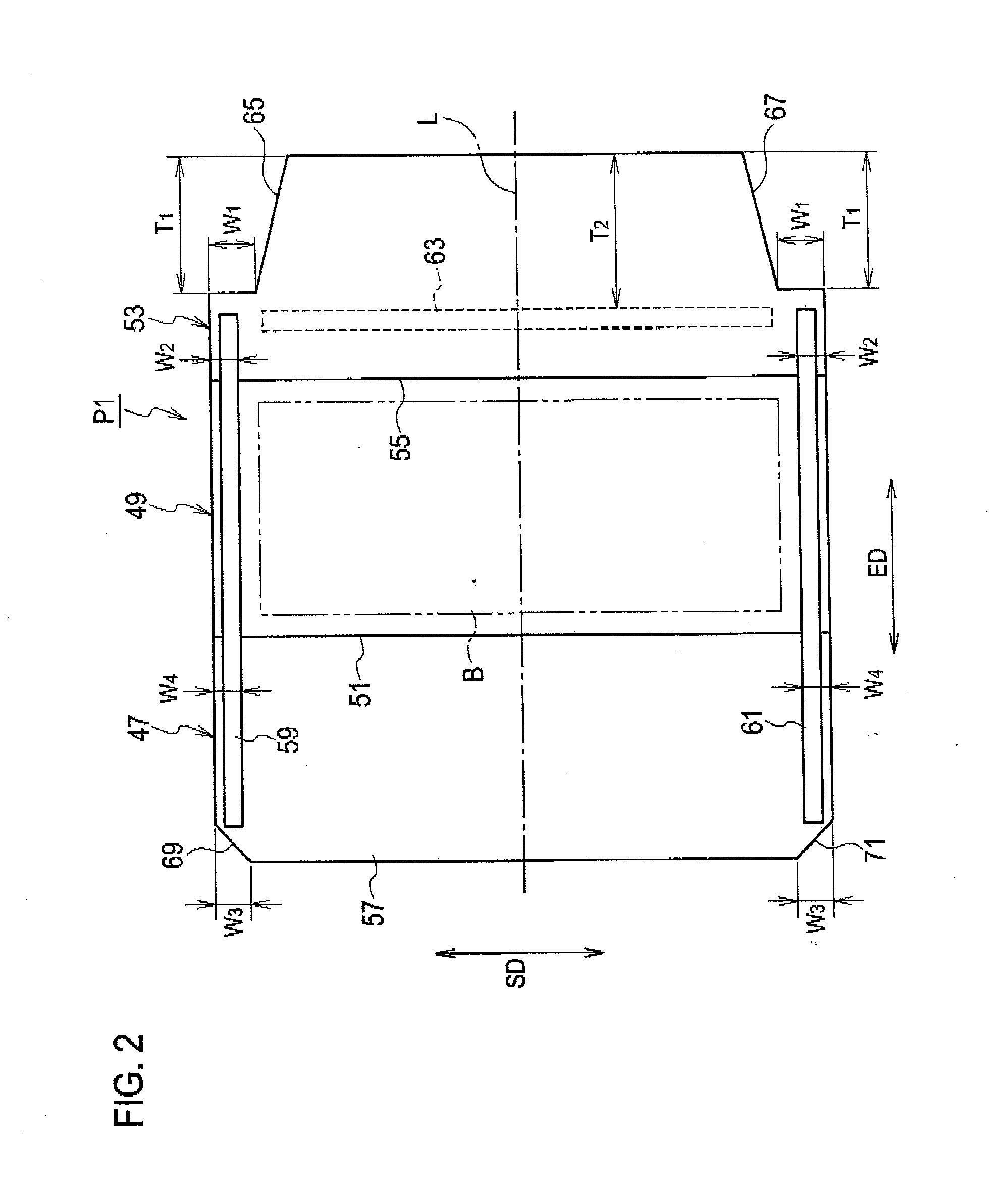
[0044]An envelope sheet according to the first embodiment of the present invention will be described, referring to FIGS. 2 to 5.

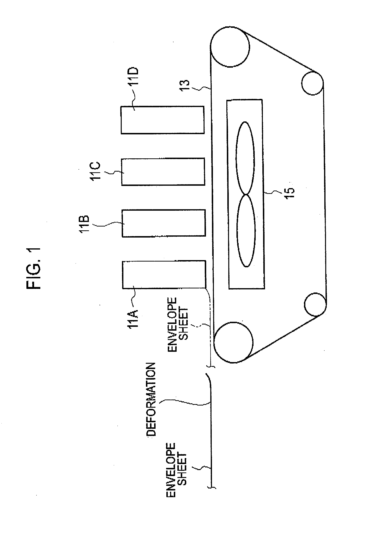
[0045]As shown in FIGS. 2 and 3A to 3C, the envelope sheet P1 is used when manufacturing the envelope M with the content B enclosed therein by the automatic envelope manufacturing system 1 described above (see FIG. 5). The envelope sheet P1 has a first rectangular component sheet (first component sheet) 47. To the first component sheet 47, a second rectangular component sheet (second component sheet) 49 is consecutively connected along the envelope unfolding direction (sheet long side direction) ED via the first folding line 51. To the second component sheet 49, a third rectangular component sheet (third component sheet) 53 is consecutively connected along the envelope unfolding direction ED via the second folding line 55. In other words, the three component sheets 47, 49 and 53 are consecutively connected along the envelope unfolding direction ED via the t...

second embodiment

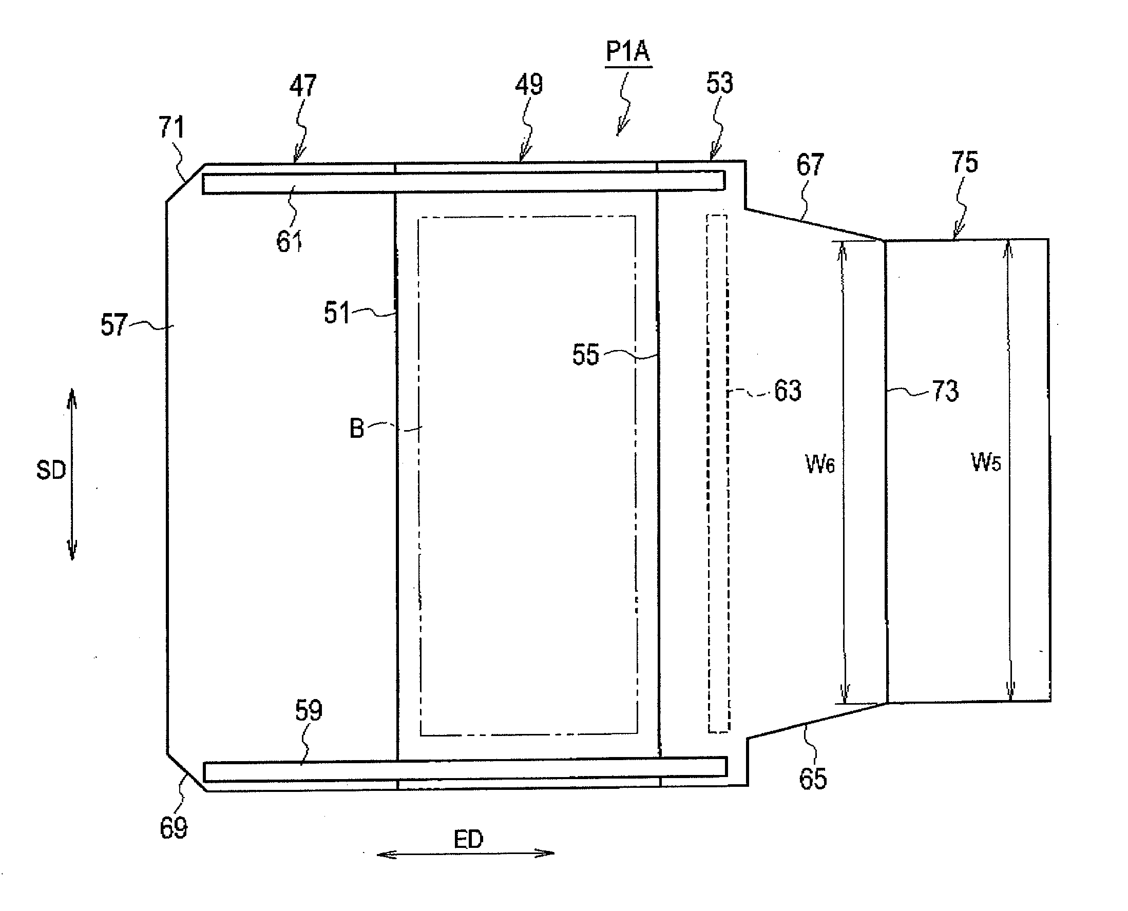
[0055]An envelope sheet according to the second embodiment of the present invention will be described, referring to FIGS. 7, 8A, 86 and 8C.

[0056]As shown in FIGS. 7 and 8A to 8C, an envelope sheet P1A is used when manufacturing an envelope with the content B enclosed therein by the automatic envelope manufacturing system 1 described above (see FIG. 5). The envelope sheet P1A has a configuration similar to that of the envelope sheet P1 according to the first embodiment of the present invention (see FIG. 1) except for the following points. Note that, for the plurality of components in the envelope sheet P1A, those corresponding to the components in the envelope sheet P1 are provided with identical reference numerals.

[0057]The envelope sheet P1A according to the second embodiment of the present invention has, in addition to the first component sheet 47, the second component sheet 49, and the third component sheet 53, a fourth rectangular component sheet 75 consecutively connected to th...


PUM


Abstract

Another coating part is formed along a sheet short side direction, on a region which is a part of an envelope outer side of a third component sheet and which contacts a flap by folding along a second folding line. A first cutout part and a second cutout part which respectively extend in an extension direction of a first coating part and a second coating part, are respectively formed on both side fringes in the sheet short side direction in the third component sheet. The minimum width of each of the first cutout part and the second cutout part in the sheet short side direction is set longer than a length from the side fringe of the envelope sheet in the sheet short side direction to the inner side fringe of each of the first coating part and the second coating part.

Description

CROSS REFERENCE TO RELATED APPLICATION[0001]This application claims benefit of priority under 35 U.S.C. §119 to Japanese Patent Application No. 2012-030297 filed on Feb. 15, 2012, the entire contents of which are incorporated by reference herein.BACKGROUND OF THE INVENTION[0002]1. Field of the Invention[0003]The present invention relates to an envelope sheet used for manufacturing an envelope.[0004]2. Description of the Related Art[0005]In recent years, along with expanding use of envelopes for direct mails or the like, various types of envelope sheets used when manufacturing envelopes with an automatic envelope manufacturing system have been developed (Patent Document 1: Japanese Patent Application Laid-Open Publication No. 2000-343892). The configuration of an envelope sheet according to prior art is as follows.[0006]The envelope sheet according to prior art has a first rectangular component sheet. A second rectangular component sheet is consecutively connected to the first compon...

Claims


Application Information

Patent Timeline
Patent Type & Authority Applications(United States)
IPC IPC(8): B65D27/16
CPCB43M5/04B65D27/16B65D27/00
Inventor WAKATABI, TADAYUKI
Owner RISO KAGAKU CORP
Why Eureka
Try Eureka