Ultrasonic transducer

a transducer and short axis technology, applied in ultrasonic/sonic/infrasonic diagnostics, instruments, generators/motors, etc., can solve the problems of increasing the possibility of air entering the propagation liquid, adversely affecting the ultrasonic image obtained by ultrasonic diagnostics, and increasing the internal pressure in the housing

Active Publication Date: 2013-08-15
NIHON DEMPA KOGYO CO LTD
View PDF1 Cites 11 Cited by
  • Summary
  • Abstract
  • Description
  • Claims
  • Application Information

AI Technical Summary

Benefits of technology

[0017]According to an aspect of this disclosure, there is provided an ultrasonic transducer. The ultrasonic transducer includes an ultrasonic transmitting and receiving portion, a housing, a driving device, a casing, a first volume compensation mechanism, a ventilating portion, a diaphragm, and a component. The housing houses the ultrasonic transmitting and receiving portion inside of the housing. The housing seals an ultrasonic propagation liquid inside of the housing. The driving device is configured to drive the ultrasonic transmitting and receiving portion. The casing houses the driving device inside of the casing. The first volume comp

Problems solved by technology

Therefore, the following failures may occur.
That is, first, in the case where a temperature of usage environment is high, the sealed propagation liquid is expanded, causing rising of the internal pressure in the housing.
Further, in the case where the temperature of usage environment becomes low after the liquid sealed at a high temperature leaks outside of the housing, the possibility of entering air into the propagation liquid increases.
The air mixed into the propagation liquid becomes an air bubble, adversely affecting an ultrasonic image obtained by an ultrasonic diagnostics.
This changes a distance (a gap) between the flat portion of the ultrasonic transmitting and receiving portion and the inner surface (the inner wall) of

Method used


Image

  • Ultrasonic transducer
  • Ultrasonic transducer
  • Ultrasonic transducer

Examples


embodiment 1

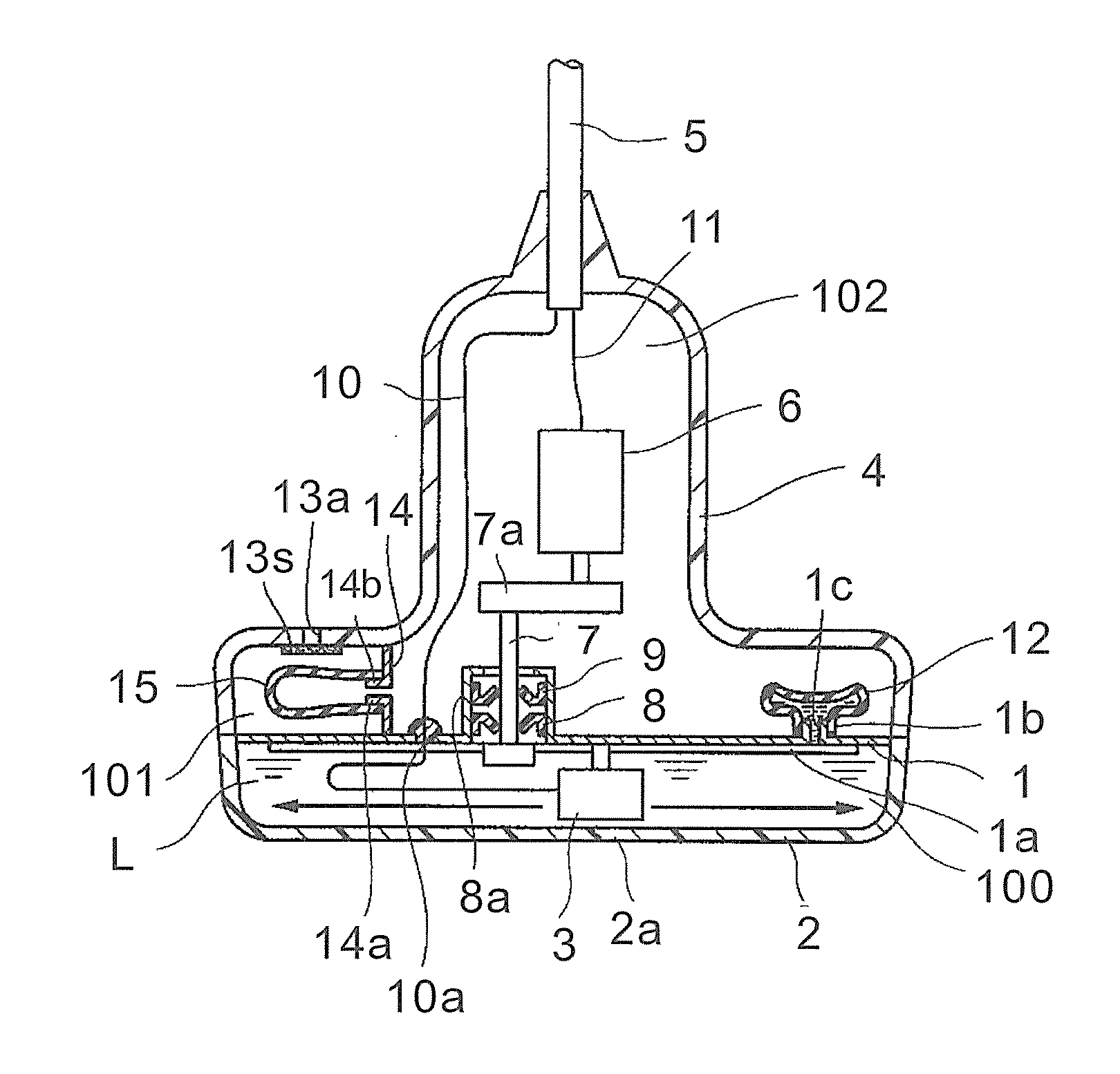
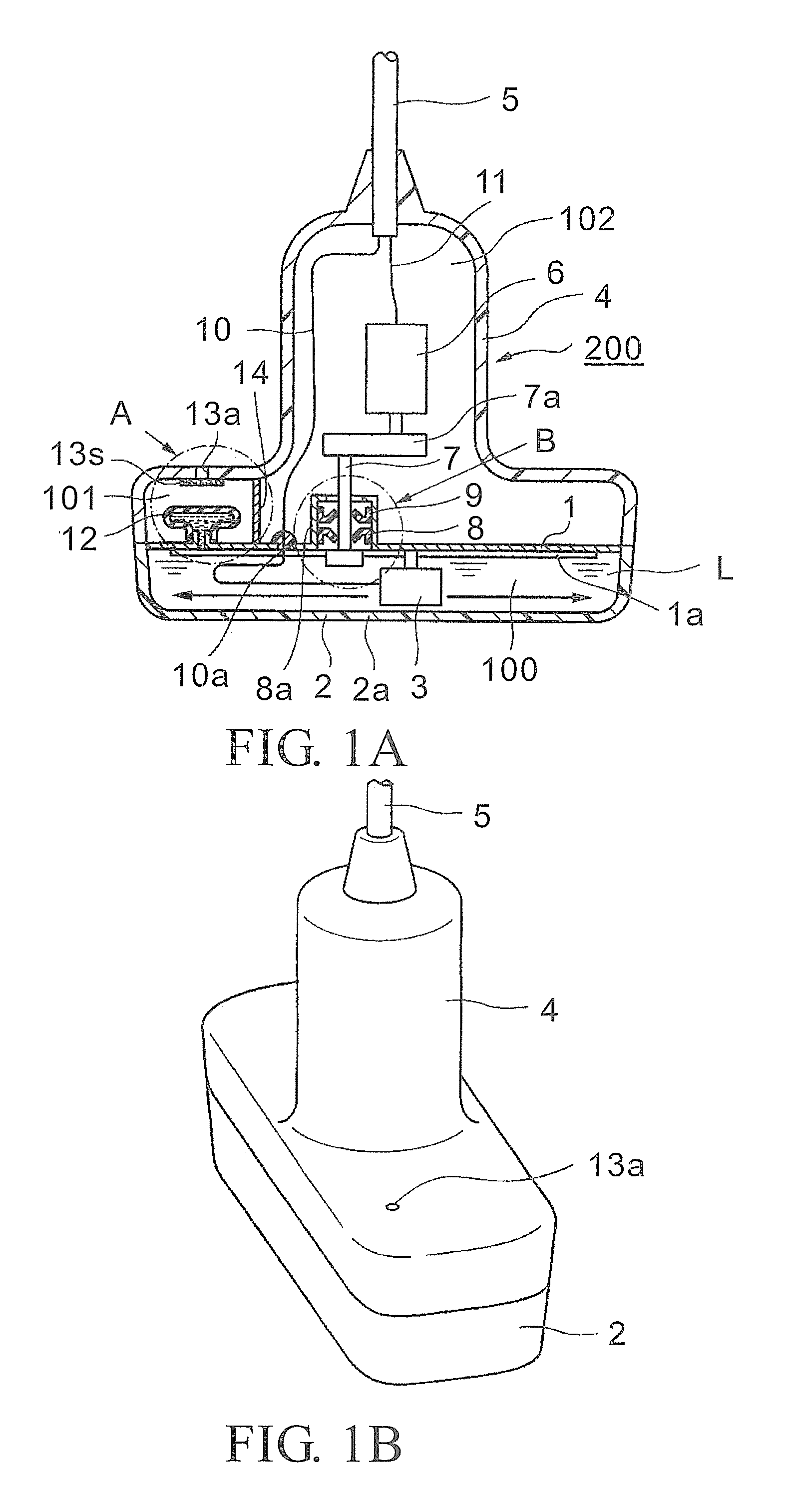
[0030]As illustrated in FIG. 1A, an ultrasonic transducer according to Embodiment 1 of this disclosure is an ultrasonic transducer 200, which includes a chassis 1, a shaft bearing portion 8a, an ultrasonic transmitting and receiving portion 3, a driving shaft 7, and a transducer driving portion. The chassis 1 is made of resin material. The shaft bearing portion 8a is vertically disposed on the top surface of the chassis 1 and integrally formed with the chassis 1. The ultrasonic transmitting and receiving portion 3 is pivotally supported to the shaft bearing portion 8a via two oil seals 8 and 9. The driving shaft 7 reciprocates the ultrasonic transmitting and receiving portion 3 along a linear guide 1 a disposed on the bottom surface of the chassis 1 in the short axis direction. The transducer driving portion includes an ultrasonic transmitting and receiving portion driving device (a drive motor) 6. The ultrasonic transmitting and receiving portion driving device (the drive motor) 6 ...

embodiment 2

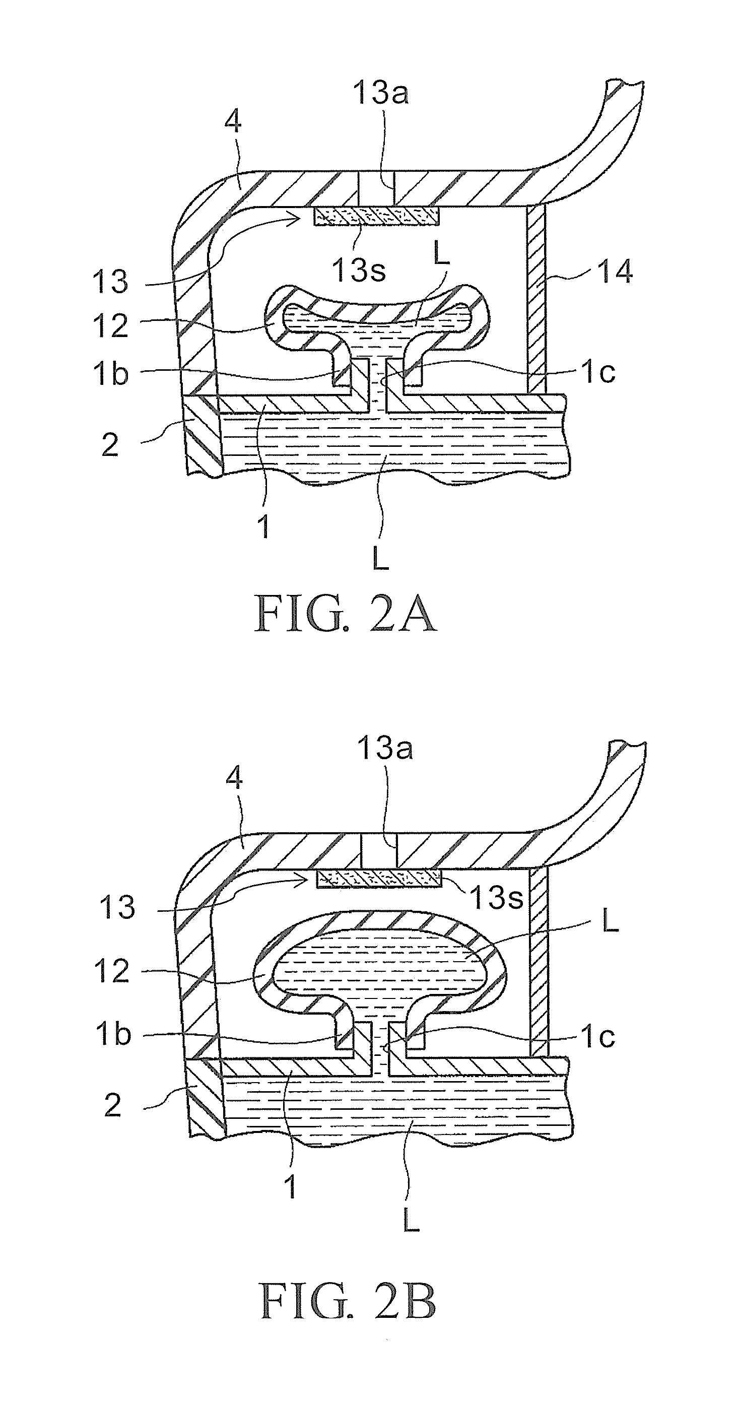
[0041]As illustrated in FIG. 4, the ultrasonic transducer according to Embodiment 2 of this disclosure includes the above-described first volume compensation mechanism 12, a diaphragm (a divider) 14, and a second volume compensation mechanism 15. The first volume compensation mechanism 12 projects from the top surface of a chassis 1 in a second internal space 102. The diaphragm (the divider) 14 is disposed between a first internal space 101 and the second internal space 102. The second volume compensation mechanism 15 fluidically communicates with the second internal space 102 via a hole 14a in the diaphragm (the divider) 14 so as to make pressure in the second internal space 102 approximately equal to atmospheric pressure.

[0042]With this structure, when the temperature of the ambient environment of the ultrasonic transducer rises, ultrasonic propagation liquid L in an ultrasonic propagation liquid chamber 100 expands and the first volume compensation mechanism 12 is operated. The f...


PUM


Abstract

An ultrasonic transducer includes an ultrasonic transmitting and receiving portion, a housing, a driving device, a casing, a first volume compensation mechanism, a ventilating portion, a diaphragm, and a component. The housing houses the ultrasonic transmitting and receiving portion, and the housing seals ultrasonic propagation liquid. The driving device is configured to drive the ultrasonic transmitting and receiving portion. The casing houses the driving device. The first volume compensation mechanism is configured to absorb a volume change of the ultrasonic propagation liquid. The diaphragm divides an internal space of the casing into at least a first internal space and a second internal space. The ventilating portion is configured to ventilate the first internal space to outside of the casing. The component is disposed in a space other than the first internal space in the internal space and includes a frame ground that electrically connects to an electrical circuit.

Description

CROSS REFERENCE TO RELATED APPLICATIONS[0001]This application claims the priority benefit of Japan application serial no. 2012-030097, filed on Feb. 15, 2012. The entirety of the above-mentioned patent application is hereby incorporated by reference herein and made a part of this specification.TECHNICAL FIELD[0002]This disclosure relates to a short axis mechanical scan type ultrasonic transducer where an ultrasonic transmitting and receiving portion is mechanically reciprocated in the short axis direction and the linear direction to perform ultrasonic diagnostics of a test object. Especially, this disclosure relates to an ultrasonic transducer that prevents entrance of air in ultrasonic propagation liquid and prevents deformation of a portion of a housing contacting the test object due to change in internal pressure caused by temperature change of the ultrasonic propagation liquid in the housing where the ultrasonic transducer is housed.DESCRIPTION OF THE RELATED ART[0003]A short ax...

Claims


Application Information

Patent Timeline
IPC IPC(8): H01L41/053
CPCH01L41/0533G01N29/24A61B8/4281A61B8/4461A61B8/546A61B8/00H10N30/883
Inventor NAKA, YOJI
Owner NIHON DEMPA KOGYO CO LTD
Why Eureka
Try Eureka