System and method for reactive power regulation

Active Publication Date: 2013-08-15
GENERAL ELECTRIC CO
View PDF9 Cites 30 Cited by
  • Summary
  • Abstract
  • Description
  • Claims
  • Application Information

AI Technical Summary

Benefits of technology

[0008]In accordance with one embodiment disclosed herein, a system is provided for performing reactive power control. The system includes a power converter and a controller coupled to the power converter. The power converter is coupled between a power source and an electrical grid. The power converter is configured to convert a first form of electric power generated from the power source to a second form of electric power suitable to be distributed by the electrical grid. The controller is configured to monitor the electric power transmitted between the power converter and the electrical grid. The controller is further configured to decouple a positive seq

Problems solved by technology

However, in an imbalanced electrical grid, the negative sequence components may lead to second order ripples in the output power.
Therefore, the reactive power control is not accurate due to

Method used


Image

  • System and method for reactive power regulation
  • System and method for reactive power regulation
  • System and method for reactive power regulation

Examples


Embodiment Construction

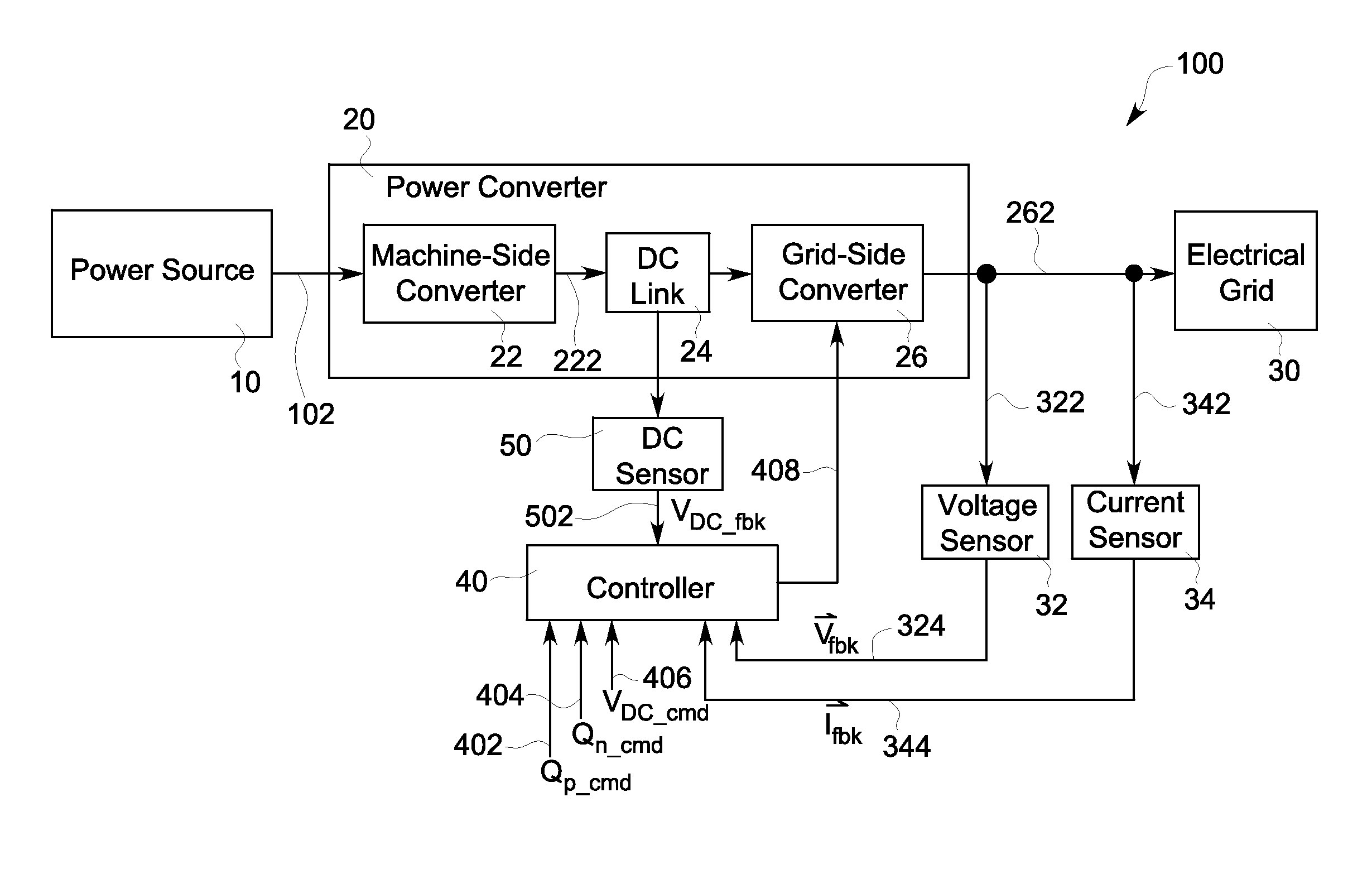
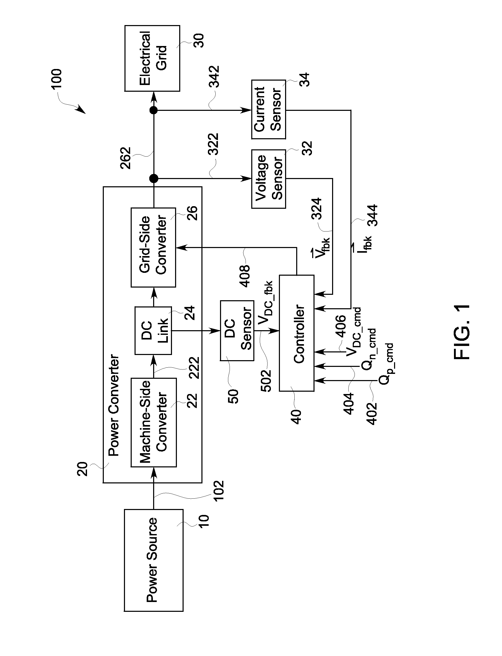
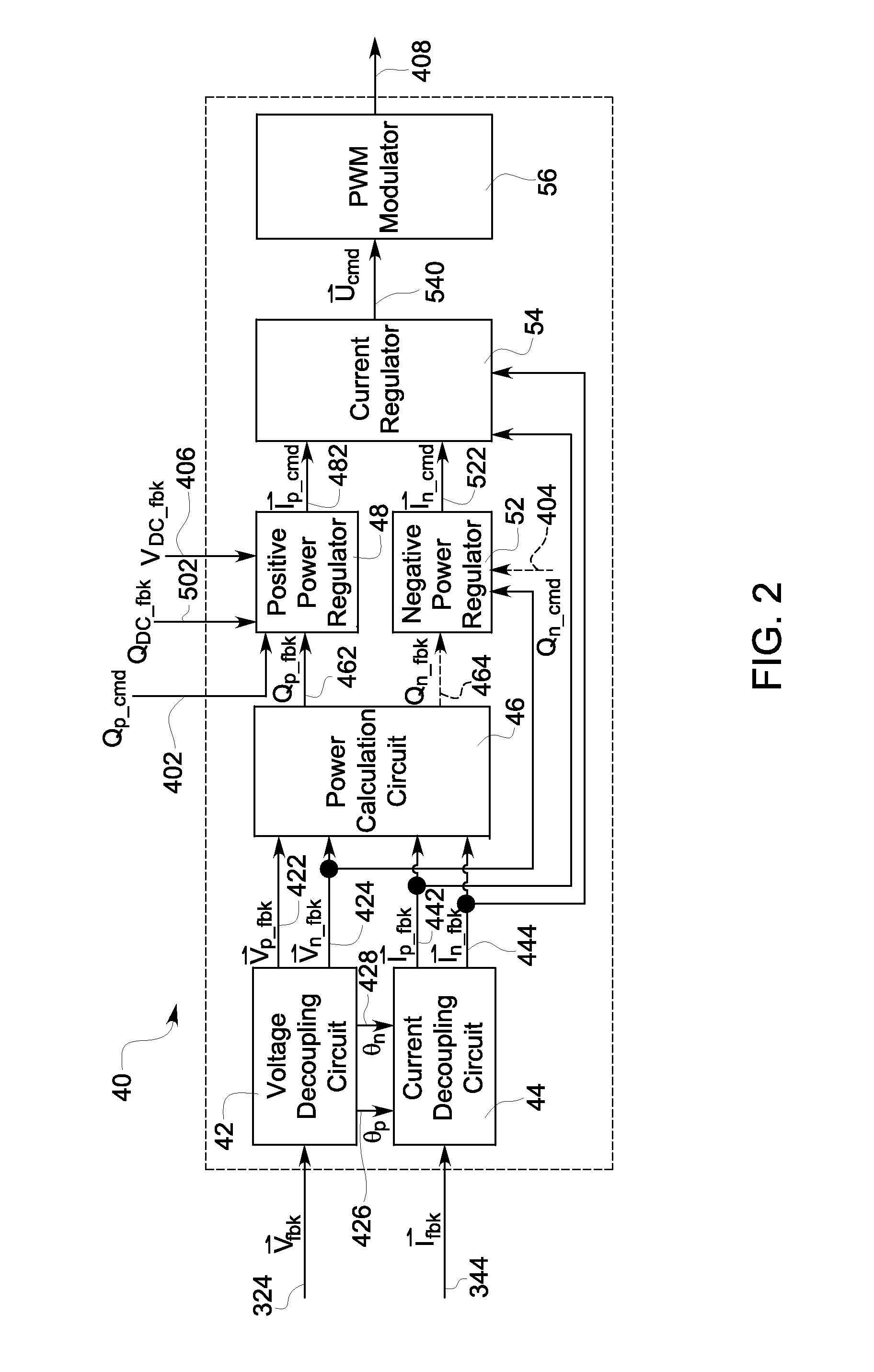
[0028]Embodiments disclosed herein relate to a system and method for reactive power regulation. In one aspect, the system and method are implemented by decoupling positive sequence components and negative sequence components of the system output power. The system and method are further implemented by separately regulating reactive power with respect to the positive sequence and the negative sequence for controlling the reactive power more accurately and thereby stabilizing the electrical grid and mitigating grid imbalance. As the positive reactive power and negative reactive power are independently regulated, the terms “vector VAR control” or “vector VAR regulation” are introduced herein. These terms are not intended to limit the scope of the disclosure of reactive power control only as, in some implementations, “vector VAR control” may also include active power control or active power regulation.

[0029]Unless defined otherwise, technical and scientific terms used herein have the sam...


PUM


Abstract

A system and method are provided for performing reactive power control. The system includes a power converter and a controller coupled to the power converter. The power converter is configured to convert a first form of electric power generated from the power source to a second form of electric power suitable to be distributed by the electrical grid. The controller is configured to monitor the electric power transmitted between the power converter and the electrical grid. The controller is further configured to decouple a positive sequence component and a negative sequence component from the monitored electric power. The controller is further configured to perform a positive reactive power control and a negative reactive power control with respect to the decoupled positive and negative sequence components. The controller is further configured to transmit a control signal to the power converter based on the positive and negative reactive power control.

Description

BACKGROUND OF THE INVENTION[0001]1. Field of the Invention[0002]The field of the invention relates generally to power regulation, and more particularly relate to reactive power regulation.[0003]2. Description of Related Art[0004]Power sources such as solar panels and wind turbines have received increased attention as environmentally safe and sustainable alternative power sources compared to traditional coal powered power sources. When the power output from the power sources is fed to an electrical grid for transmission and distribution, it is usually necessary to control the reactive power of the output power to fulfill electrical demand while providing stability for the electrical grid.[0005]Conventional reactive power control is based on the assumption that the electrical grid is always symmetrical in three phases. Based on this assumption, the reactive power is regulated by directly adjusting the output power in positive sequence components without considering negative sequence c...

Claims


Application Information

Patent Timeline
IPC IPC(8): G05F1/70
CPCG05F1/70Y02E40/30H02J3/1835
Inventor YUAN, XIAOMINGTAN, ZHUOHUIKLODOWSKI, ANTHONY MICHAEL
Owner GENERAL ELECTRIC CO
Why Eureka
Try Eureka