Check patentability & draft patents in minutes with Patsnap Eureka AI!

Charge Pump Circuit

Inactive Publication Date: 2013-08-15
ASAHI KASEI ELECTRONICS CO LTD
View PDF4 Cites 8 Cited by
  • Summary
  • Abstract
  • Description
  • Claims
  • Application Information

AI Technical Summary

Benefits of technology

The present invention aims to prevent the generation of noise in a power source input or ground by preventing a sudden increase or decrease in current flow. The invention achieves this by operating multiple charge pump units in parallel, where one or more units are always in a period where current is flowing. This prevents spikes in current and ensures that noise generated due to changes in current is minimized, which prevents circuit performance degradation.

Problems solved by technology

Since a current flowing between the input power source and ground is changed by an operation of the charge pump circuit, along with the operation thereof, the noise is generated in the input power source and the ground.

Method used


Image

  • Charge Pump Circuit
  • Charge Pump Circuit
  • Charge Pump Circuit

Examples


second embodiment

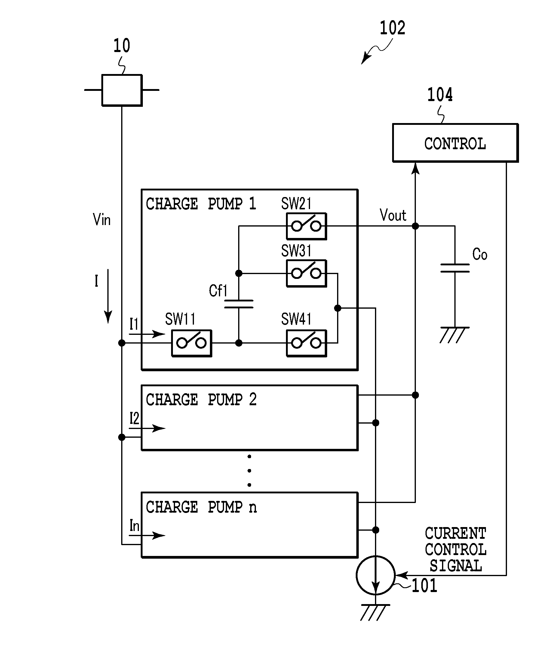
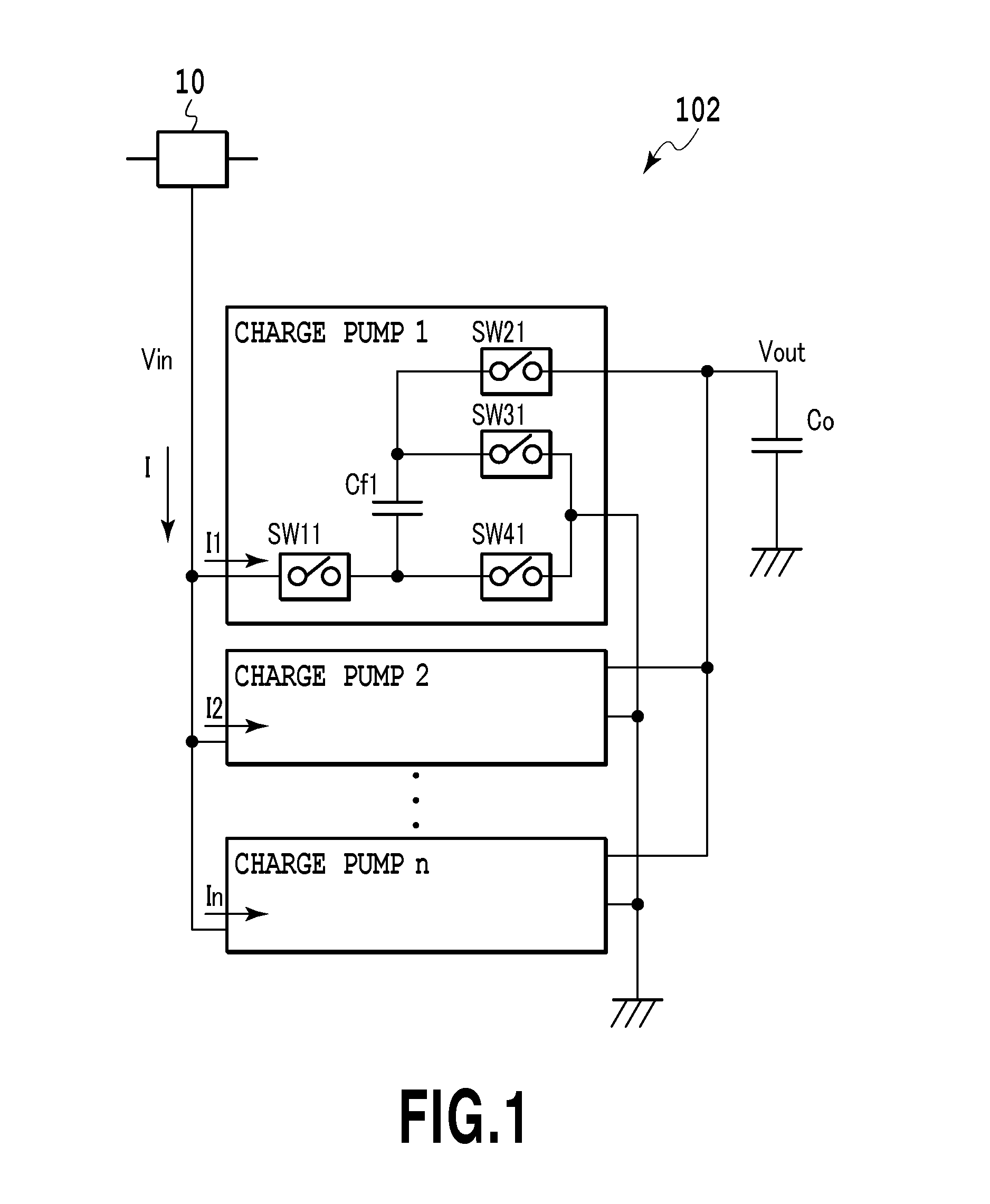
[0050]The charge pump circuit 102 according to the first embodiment illustrated in FIG. 3 is an example where the current source 101 is inserted between the positive voltage input terminals of the charge pump units 1 to n and the positive input power source. However, as with a second embodiment illustrated in FIG. 8, the second embodiment where the current source 101 is inserted between ground input terminals that are negative voltage input terminals of the charge pump units 1 to n and the ground that is a negative input power source can provide a similar operation effect to that of the first embodiment.

third embodiment

[0051]With reference to FIG. 9, another embodiment of the present invention will be descried below.

[0052]FIG. 9 is a circuit diagram of a third embodiment of the charge pump circuit according to the present invention.

[0053]The charge pump circuit 102 has a configuration using a control circuit that senses the load current, and includes the charge pump units 1 to n, the current source 101 connected between the positive input voltage terminals of the charge pump units 1 to n and the positive input power source, and the control circuit 104.

[0054]In the charge pump circuit illustrated in FIG. 9, the current control signal that is the output signal of the control circuit 104 performs the substantially same work as that of the current control signal that is the output signal of the control circuit 103 according to the above-described embodiment, and controls the current flowing in the current source 101 to the constant value according to the load current of the charge pump circuit 102. Wi...

fourth embodiment

[0059]The charge pump circuit according to the third embodiment illustrated in FIG. 9 is an example where, when the control circuit 104 is used, the current source 101 is inserted between the positive voltage input terminals of the charge pump units and the positive input power source. However, as with a fourth embodiment illustrated in FIG. 11, the fourth embodiment having a configuration in which the current source 101 is inserted between the ground input terminals that are the negative voltage input terminals of the charge pump units and the ground that is a negative input power source can provide the similar operation effect to that of the third embodiment.

[0060]Note that, according to the above-described embodiment, the charge pump units 1 to n refer to negative voltage generating charge pumps for stepping-down the voltage to be input, but, in place of the negative voltage generating charge pumps, positive voltage generating charge pumps for stepping-up the voltage to be input ...


PUM


Abstract

A charge pump circuit according to the present invention includes a plurality of charge pump units each including a capacitor and connected to each other in parallel; a current source connected to commonly connected power source terminals of the plurality of charge pump units; and a control circuit connected to commonly connected output terminals and controlling an amount of a current to be supplied by the current source to the commonly connected power source terminals based on an output signal at the output terminals output signal from the plurality of charge pump units. Always in at least one charge pump unit, a current from the current source via the power source terminal is supplied to the capacitor. A spike noise due to a change in current is not generated and characteristics degradation of the other circuit can be prevented.

Description

CROSS-REFERENCE TO RELATED APPLICATIONS[0001]This application claims the benefit of Japanese Patent Application Nos. 2012-029589, filed Feb. 14, 2012 and 2012-273615, filed Dec. 14, 2012, which are hereby incorporated by reference herein in their entirety.BACKGROUND OF THE INVENTION[0002]1. Field of the Invention[0003]The present invention relates to a charge pump circuit and more specifically, to a charge pump circuit that does not generate noise due to a change in current and can prevent characteristics degradation.[0004]2. Description of the Related Art[0005]Conventionally, a charge pump circuit has been directly connected to an input power source. Since a current flowing between the input power source and ground is changed by an operation of the charge pump circuit, along with the operation thereof, the noise is generated in the input power source and the ground. Thus, a current variation along with the operation of the charge pump circuit causes characteristics degradation of o...

Claims


Application Information

Patent Timeline
IPC IPC(8): G05F1/10
CPCG05F1/10H02M1/15H02M3/07H02M1/0045
Inventor MATSUOKA, DAISUKE
Owner ASAHI KASEI ELECTRONICS CO LTD
Features
  • R&D
  • Intellectual Property
  • Life Sciences
  • Materials
  • Tech Scout
  • Unparalleled Data Quality
  • Higher Quality Content
  • 60% Fewer Hallucinations
Learn More