Driver drowsiness prediction system and method thereof

a technology of driver drowsiness and prediction system, which is applied in the field of vital signal detection system, can solve the problems of driver unwillingness to use such types of anti-drowsiness system, and the inability of drivers to guarantee the keeping of drivers, and achieve the effect of reducing the probability of driver drowsiness

Inactive Publication Date: 2013-08-15
WISTRON CORP
View PDF9 Cites 9 Cited by
  • Summary
  • Abstract
  • Description
  • Claims
  • Application Information

AI Technical Summary

Benefits of technology

[0009]Aiming at the driver awakening process in the conventional technology and the risk of failing to awaken a driver and instead allowing the drive

Problems solved by technology

Driver fatigue is one of the major reasons for traffic accidents.
When fatigued, the driver usually enters a dozing condition, resulting in traffic accidents.
Among these methods, since the detections of the driver's head and the driver's eye blinking frequency usually have misjudging problems, drivers are unwilling to use such types of anti-drowsines

Method used


Image

  • Driver drowsiness prediction system and method thereof
  • Driver drowsiness prediction system and method thereof
  • Driver drowsiness prediction system and method thereof

Examples


first embodiment

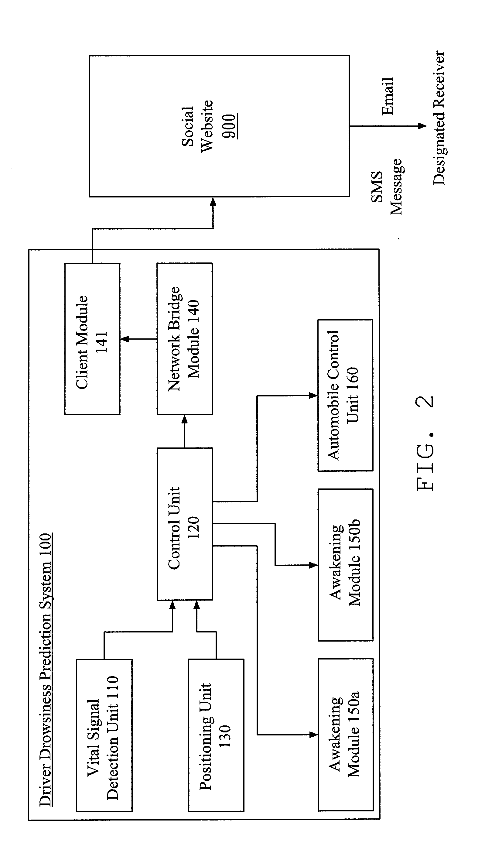
[0022]Please refer to FIG. 2, which is an explanatory system block diagram of a driver drowsiness prediction system according the disclosure. The driver drowsiness prediction system is adapted to be detectable on conscious statuses of a driver and alarmable if the driver is near unconsciousness.

[0023]As shown in FIG. 2, a driver drowsiness prediction system 100 includes a vital signal detection unit 110, a control unit 120, a positioning module 130, a network bridge module 140, one or more awakening module 150a, 150b and an automobile control module 160. The vital signal detection unit 110, positioning module 130, network bridge module 140, awakening module 150a, 150b and automobile control module 160 are connected with control unit 120 through wired connection or wireless connection; wireless connection includes Bluetooth communication protocol, 2.4 GHz radio frequency or wireless AD-Hoc network.

[0024]As shown in FIG. 2, the vital signal detection unit 110 is used to detect and mea...

second embodiment

[0039]Please refer to FIG. 3, which is an explanatory system block diagram of another driver drowsiness prediction system according the disclosure driver. A drowsiness prediction system 200 is adapted to be detectable on conscious statuses of a driver and alarmable if the driver is near unconsciousness. The driver drowsiness prediction system 200 includes a brainwave instrument 210, a control unit 220, a positioning module 230, a network bridge module 240, an awakening module 250 and an automobile control module 260; wherein, the control unit 220 includes a signal analyzing unit 221 and a controller 222.

[0040]As shown in FIG. 3, the brainwave instrument 210 is to measure the driver's brainwaves; the brainwave instrument 210 connects with the signal analyzing unit 221 to send brainwaves to the signal analyzing unit 221.

[0041]The signal analyzing unit 221 receives and analyzes the brainwaves, so as to determine whether the driver is near unconsciousness or remains awake. The signal an...


PUM


Abstract

A driver drowsiness prediction system includes a vital signal detection unit, a control unit and a network bridge module. The vital signal detection unit detects vital signals of a driver. The control unit receives the driver's vital signs, and stores at least a feature signal. The feature signal represents the vital signal pattern of losing consciousness. The control unit continuously compares the detected vital signal with the feature signal. When the vital signal is similar to the feature signal, the control unit issues a pre-alarming command. The network bridge module receives the pre-alarming command and is triggered to perform a network connection process. The network bridge module logs into a pre-determined social website according to a login script, and then sends a pre-alarming message thereon, wherein the pre-alarming message includes an event indicating the driver is near unconsciousness.

Description

CROSS-REFERENCES TO RELATED APPLICATIONS[0001]This non-provisional application claims priority under 35 U.S.C. §119(a) on Patent Application No. 101104943 filed in Taiwan, R.O.C. on 2012 Feb. 15, the entire contents of which are hereby incorporated by reference.BACKGROUND[0002]1. Technical Field[0003]The disclosure relates to a vital signal detection system, and more particularly to a driver drowsiness prediction system and method thereof.[0004]2. Related Art[0005]Driver fatigue is one of the major reasons for traffic accidents. When fatigued, the driver usually enters a dozing condition, resulting in traffic accidents.[0006]FIG. 1 shows a basic process for a drowsiness preventing system in the conventional technology. Such a drowsiness preventing system must obtain and further analyze the driver's vital signs, as shown in Step 1 and Step 2. Such a drowsiness preventing system determines if the driver is dozing according the analysis result of the vital signals, as shown in Step 3. ...

Claims


Application Information

Patent Timeline
IPC IPC(8): G08B21/06
CPCY02T10/84G08B21/06A61B5/18A61B5/24G08G1/096716
Inventor LI, CHIA-HSIENCHANG, YAO-TSUNGLIN, PAI-YANG
Owner WISTRON CORP
Why Eureka
Try Eureka