Radio measurement collection method, radio terminal, and radio base station

Active Publication Date: 2013-08-15
KYOCERA CORP
View PDF9 Cites 13 Cited by
  • Summary
  • Abstract
  • Description
  • Claims
  • Application Information

AI Technical Summary

Benefits of technology

[0008]Therefore, an object of the present invention is to provide a radio measurement collection method, a radio terminal, an

Problems solved by technology

However, in the radio measurement collection method, since all types of measurement data are handled in the same manner, it i

Method used


Image

  • Radio measurement collection method, radio terminal, and radio base station
  • Radio measurement collection method, radio terminal, and radio base station
  • Radio measurement collection method, radio terminal, and radio base station

Examples


Example

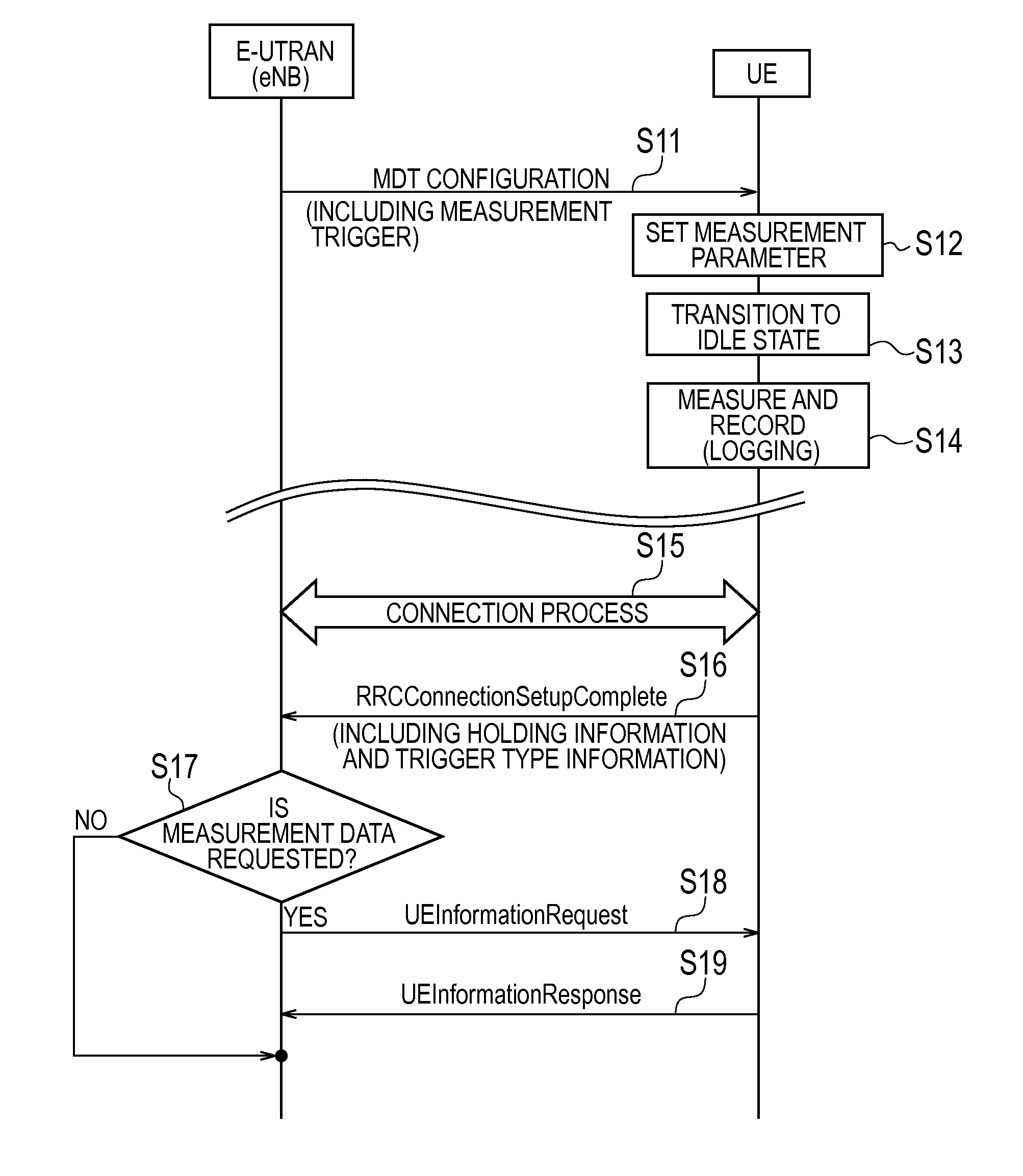
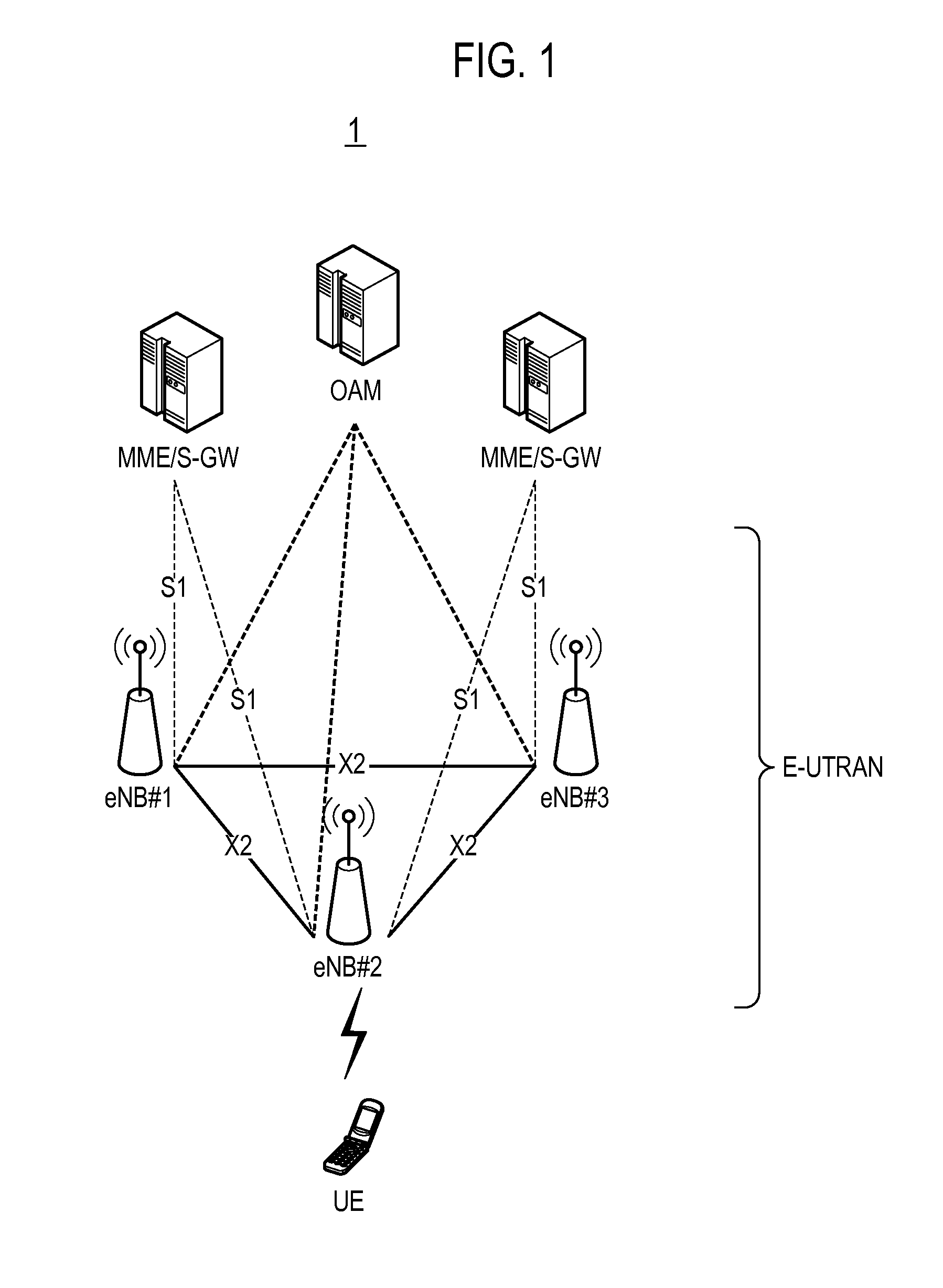
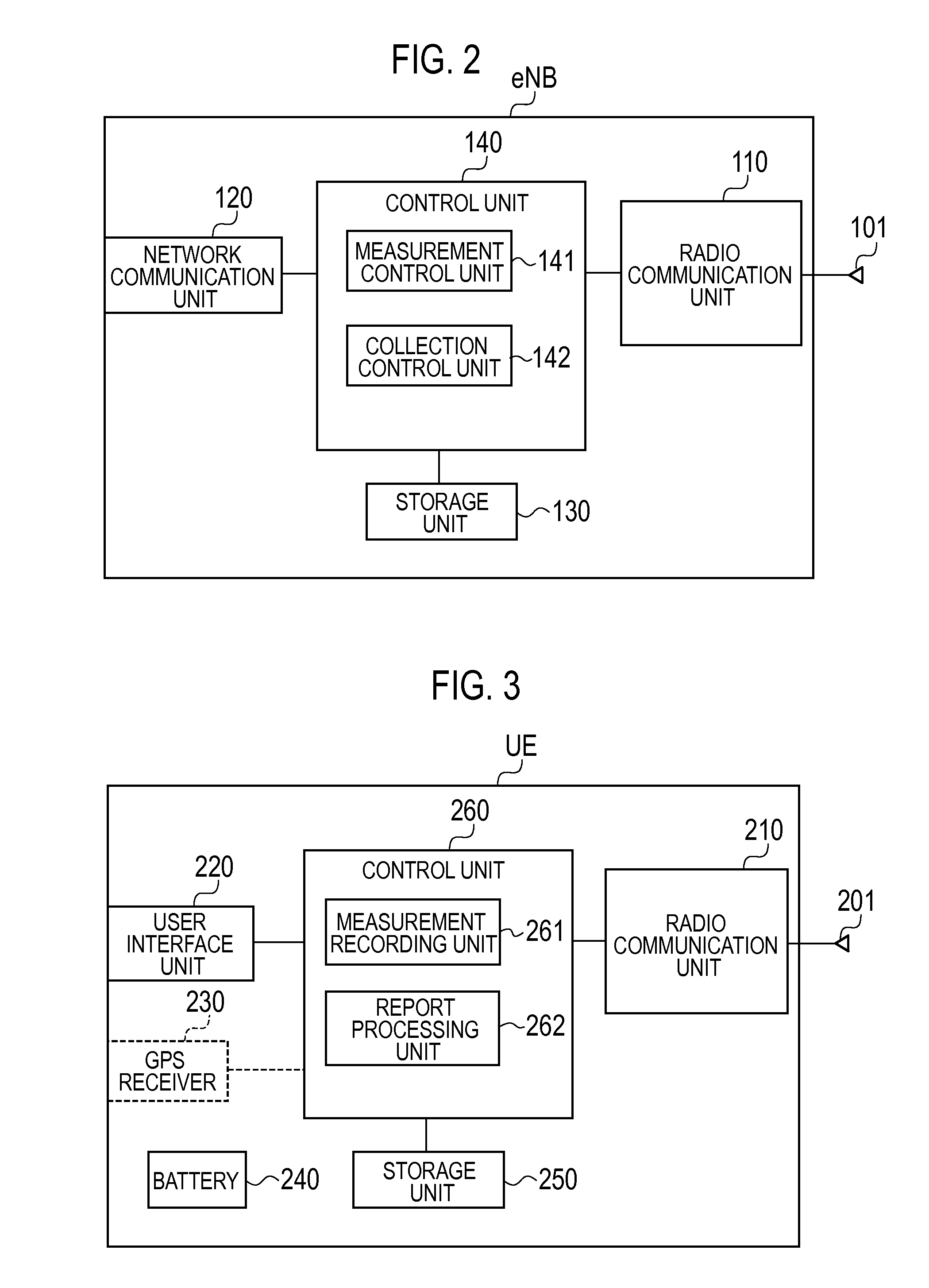
[0026]With reference to the accompanying drawings, an embodiment of the present invention will be described in the sequence of (1) Overview of mobile communication system, (2) Configuration of radio base station, (3) Configuration of ratio terminal, (4) Radio measurement collection method, (5) Effect of embodiment, and (6) Other embodiments. It is to be noted that the same or similar reference numerals are applied to the same or similar parts through the drawings in the following embodiments.

[0027]A radio measurement collection method according to the present embodiment includes: a step of transmitting, by a network including a radio base station, a setup message including a measurement trigger to a radio terminal; a step of setting, by the radio terminal, the measurement trigger included in the setup message received from the network in the radio terminal, and then performing radio environment measurement when an event corresponding to the measurement trigger occurs in an idle stat...


PUM


Abstract

In one embodiment, a radio measurement collection method comprises: a step S11 of transmitting, by a E-UTRAN, a MDT Configuration message including a measurement trigger to the radio terminal UE; a step S14 of setting, by the radio terminal UE, the measurement trigger included in the MDT Configuration message received from the E-UTRAN in the radio terminal, and then performing radio environment measurement when an event corresponding to the measurement trigger occurs in an idle state and recording measurement data including a result of the measurement and location information; a step of S16 of transmitting, by the radio terminal UE, trigger type information indicating the measurement trigger to the E-UTRAN when the radio terminal UE is transitioned to a connected state from the idle state; and a step S17 of determining, by the E-UTRAN, whether to request the radio terminal UE to transmit the measurement data on the basis of the trigger type information from the radio terminal UE.

Description

TECHNICAL FIELD[0001]The present invention relates to a radio measurement collection method, a radio terminal, and a radio base station by which it is possible to measure a radio environment and collect a measurement result and location information.BACKGROUND ART[0002]In case of mobile communication systems, if a building is constructed on the periphery of a radio base station and if the installation situation of the base stations on the periphery of the radio base station changes, then the radio environment related to this radio base station changes. Therefore, conventionally, an operator performs a drive test of measuring a radio environment using a measurement vehicle provided with a measurement equipment, and collecting a measurement result and location information.[0003]Such measurement and collection, for example, may contribute to the optimization of the coverage of a radio base station, but face the problem of too many man-hours and high cost. In this regard, according to 3G...

Claims


Application Information

Patent Timeline
IPC IPC(8): H04W24/08
CPCH04W16/18H04W24/10H04W24/08
Inventor FUKUTA, NORIYOSHI
Owner KYOCERA CORP
Why Eureka
Try Eureka