Device for folding electrode assembly

a technology of electrode assembly and folding device, which is applied in the manufacture of wound/folded electrode electrodes, cell components, and final product manufacturing, etc., can solve the problems of difficult to perform the process at predetermined rotational velocity or more, and the jelly-roll type electrode assembly is not suitable for a prismatic battery

Active Publication Date: 2013-08-15
LG ENERGY SOLUTION LTD
View PDF2 Cites 9 Cited by
  • Summary
  • Abstract
  • Description
  • Claims
  • Application Information

AI Technical Summary

Problems solved by technology

The jelly-roll type electrode assembly is suitable for a cylindrical battery; however, the jelly-roll type electrode assembly is not suitable for a prismatic battery or a pouch-shaped battery because the electrode active material is separated or space utilization is low.
The stacked type electrode assembly has an advantage in that the stacked type electrode assembly can be configured to have a prismatic structure; however, the stacked type electrode assembly has disadvantages in that a process for manufacturing the stacked type electrode assembly is complicated, and, when external impact is applied to the stacked type electrode assembly, electrodes of the stacked type electrode assembly are pushed with the result that a short circuit may occur in the stacked type electrode assembly.
In a case in which the compensation amount obtained using the above calculation method is applied to compensate for the position of the rotary shaft of the winding jig in the advancing direction of the web (X-axis direction), however, it is difficult to perform the process at predetermined rotational velocity or more.
In connection with this matter, referring to FIG. 4, the graph of the compensation amount has a problem in that differentiation is not possible at a point at which θ is 180 degrees, and jerk is excessive at the point.
In a case in which the rotational velocity of the winding jig is increased, however, an excessive jerk is applied to the winding device with the result that it may be necessary to frequently replace components and products may be defective.
Particularly, in a case in which the rotational velocity of the winding jig is increased twice or more than that in the general production process, which is in use, to improve process efficiency, more serious problems are caused.

Method used


Image

  • Device for folding electrode assembly
  • Device for folding electrode assembly
  • Device for folding electrode assembly

Examples


Embodiment Construction

[0068]Now, exemplary embodiments of the present invention will be described in detail with reference to the accompanying drawings. It should be noted, however, that the scope of the present invention is not limited by the illustrated embodiments.

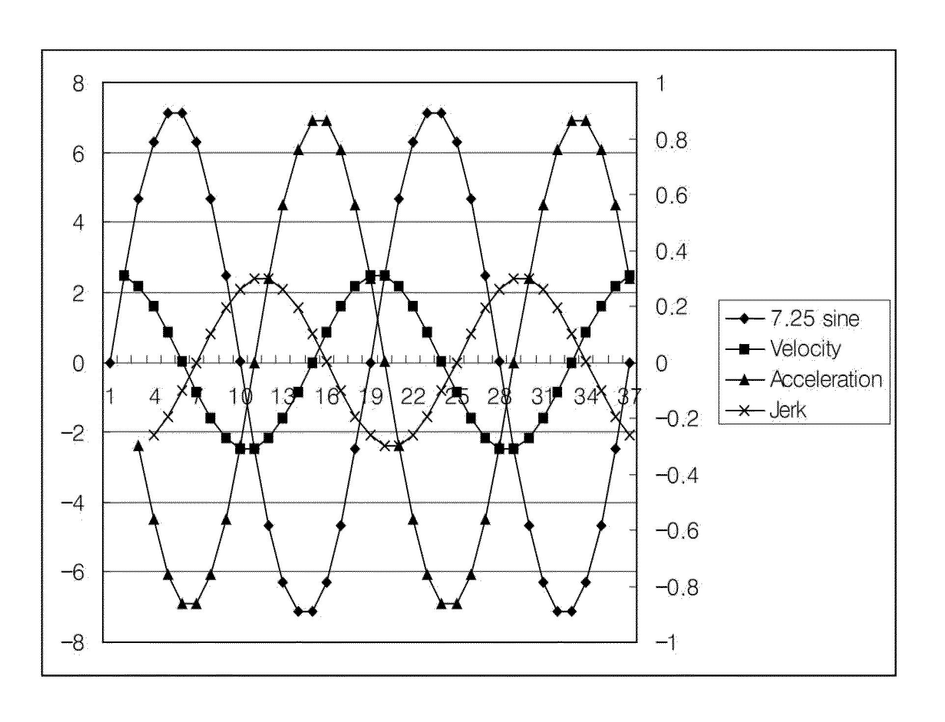
[0069]FIG. 5 is a graph showing the compensation amount, the velocity, the acceleration, and the jerk based on the rotational angle θ in a case in which compensation is performed using a periodic function (7.25 sine function) according to an embodiment of the present invention.

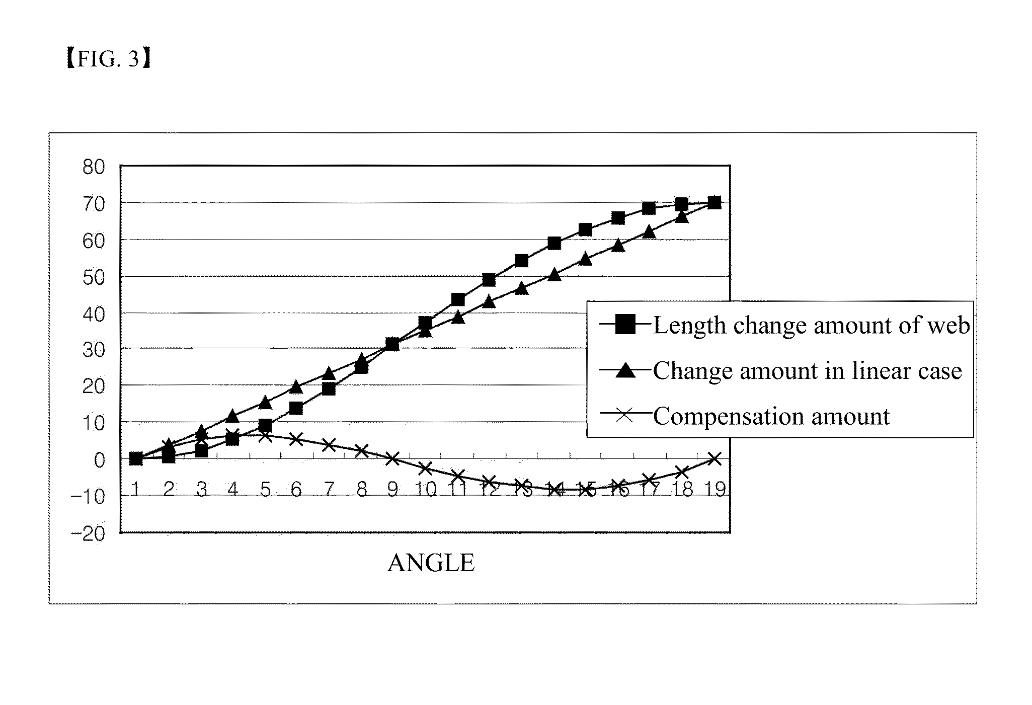
[0070]In connection with this matter, a description will be given with reference to FIGS. 2 to 4 for comparison with FIG. 5.

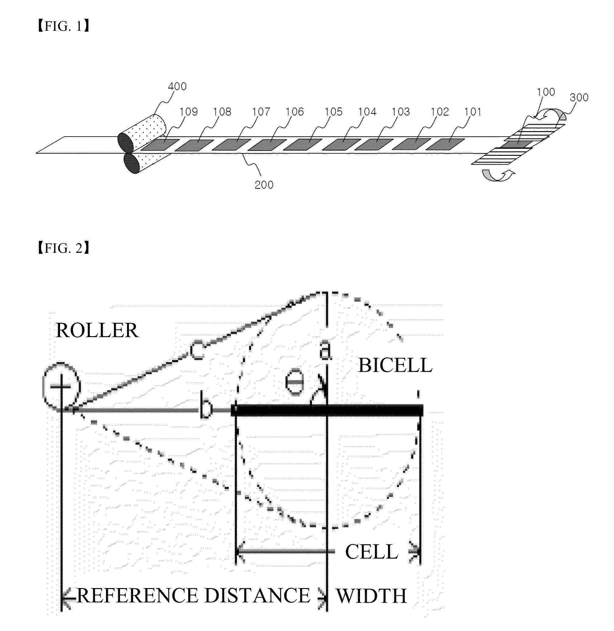
[0071]Referring to FIG. 2, the length c of a web from the roller based on an angle of the winding jig may be represented by c=(a2+b2−2ab cos θ)1 / 2 based on the change of an angle θ of the winding jig with respect to an X axis, and c0 when θ=0 may be subtracted from c to calculate a length change amount of the web.

[0072]Consequently, the length cha...


PUM

PropertyMeasurementUnit
θaaaaaaaaaa
thicknessaaaaaaaaaa
pore diameteraaaaaaaaaa

Abstract

Disclosed herein is a folding device to manufacture a stacked/folded type electrode assembly having unit cells sequentially stacked in a state in which a separation film is disposed between the respective unit cells, the folding device including a web supply unit to supply a web having plate-shaped unit cells arranged at a top of a separation film at predetermined intervals, a winding jig to rotate the unit cells while holding a first one of the unit cells of the web so that the unit cells are sequentially stacked in a state in which the separation film is disposed between the respective unit cells, and a rotary shaft compensation unit to compensate for the position of a rotary shaft of the winding jig in an advancing direction of the web (X-axis direction), wherein the rotary shaft compensation unit periodically changes the position of the rotary shaft to compensate for the change in X-axis velocity (Vx) of the web caused during winding of the plate-shaped unit cells, thereby uniformly maintaining tension of the web.

Description

TECHNICAL FIELD[0001]The present invention relates to a folding device to manufacture a stacked / folded type electrode assembly having unit cells sequentially stacked in a state in which a separation film is disposed between the respective unit cells, the folding device including a web supply unit to supply a web having plate-shaped unit cells arranged at a top of a separation film at predetermined intervals, a winding jig to rotate the unit cells while holding a first one of the unit cells of the web so that the unit cells are sequentially stacked in a state in which the separation film is disposed between the respective unit cells, and a rotary shaft compensation unit to compensate for the position of a rotary shaft of the winding jig in an advancing direction of the web (X-axis direction), wherein the rotary shaft compensation unit periodically changes the position of the rotary shaft to compensate for the change in X-axis velocity (Vx) of the web caused during winding of the plat...

Claims


Application Information

Patent Timeline
Patent Type & Authority Applications(United States)
IPC IPC(8): H01M10/04
CPCH01M10/0431H01M10/0404H01M10/0583H01M10/0459H01M10/0525Y02E60/10Y02E60/50Y02P70/50B65H51/20B65H54/10B65H59/38H01M10/052H01M4/88H01M2010/0495
Inventor MIN, KI HONGHWANG, SUNG-MINCHO, JIHOONHAN, CHANGMINSONG, KI HUNPARK, SANG HYUCKLEE, HAN SUNGKIM, BYEONG GEUNJUNG, TAE-YOONSON, JEONGSAMJUNG, SU TAEKBAIK, HYUN SUK
Owner LG ENERGY SOLUTION LTD
Why Eureka
Try Eureka