Pedicle screw assembly and method of assembly

a technology of pedicle screw and screw body, which is applied in the direction of prosthesis, ligament, osteosynthesis device, etc., can solve the problems of disruption or fracture at the screw-bone interface, high tightening torque of current pedicle screw system design, and increase manufacturing costs, so as to reduce the outside profile, and reduce the splaying force

Active Publication Date: 2013-08-15
SKELETAL DESIGN PARTNERSHIP LLC
View PDF5 Cites 63 Cited by
  • Summary
  • Abstract
  • Description
  • Claims
  • Application Information

AI Technical Summary

Benefits of technology

[0007]Advancement of the state of pedicle screw assemblies is believed desirable. This disclosed embodiment is designed to allow for adequate securement of an elongated member to a receiving housing without compromising the bone-bone screw interface that may occur when a high torque is placed onto the set screw during intraoperative assembly. Further, the disclo

Problems solved by technology

In order to clinically address the vertebral size and anatomic differences seen within the various portions of the spinal column, pedicle screw systems that are used currently frequently incorporate designs that require complex assembly steps which increase the cost of manufacturing and difficulty with intraoperative assembly.
In addition, current pedicle screw system designs typically require a high tightening torque to achieve an adequate lock on the bone screw implants.
As a result

Method used


Image

  • Pedicle screw assembly and method of assembly
  • Pedicle screw assembly and method of assembly
  • Pedicle screw assembly and method of assembly

Examples


Embodiment Construction

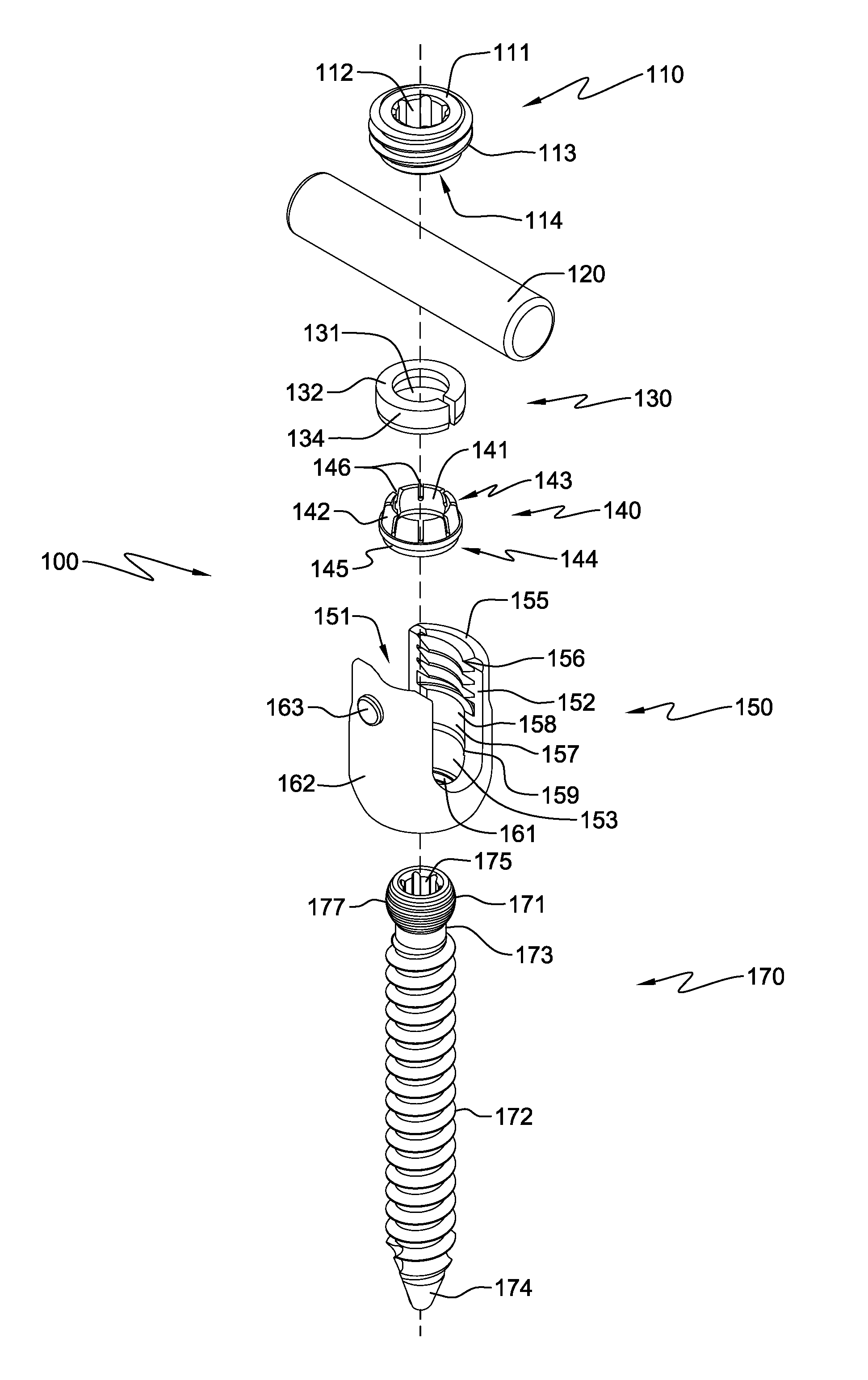
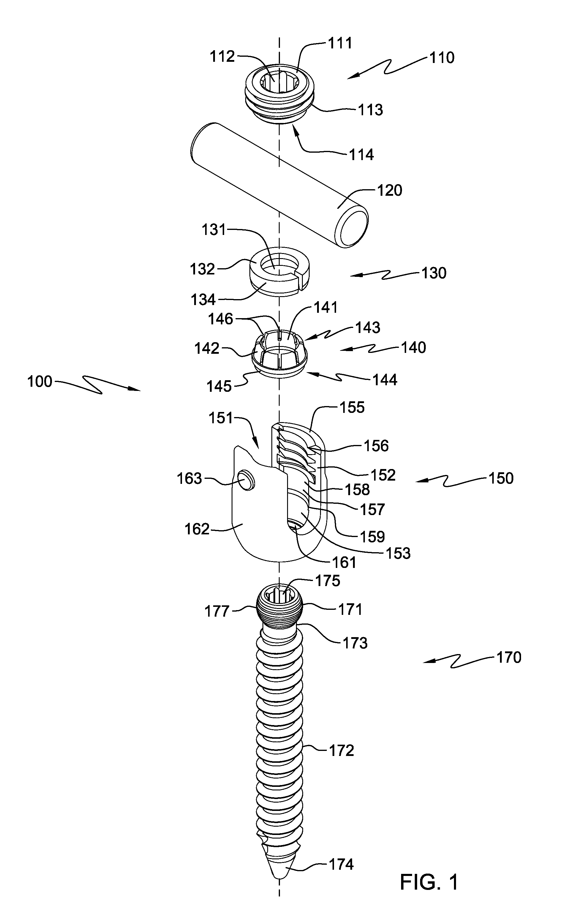
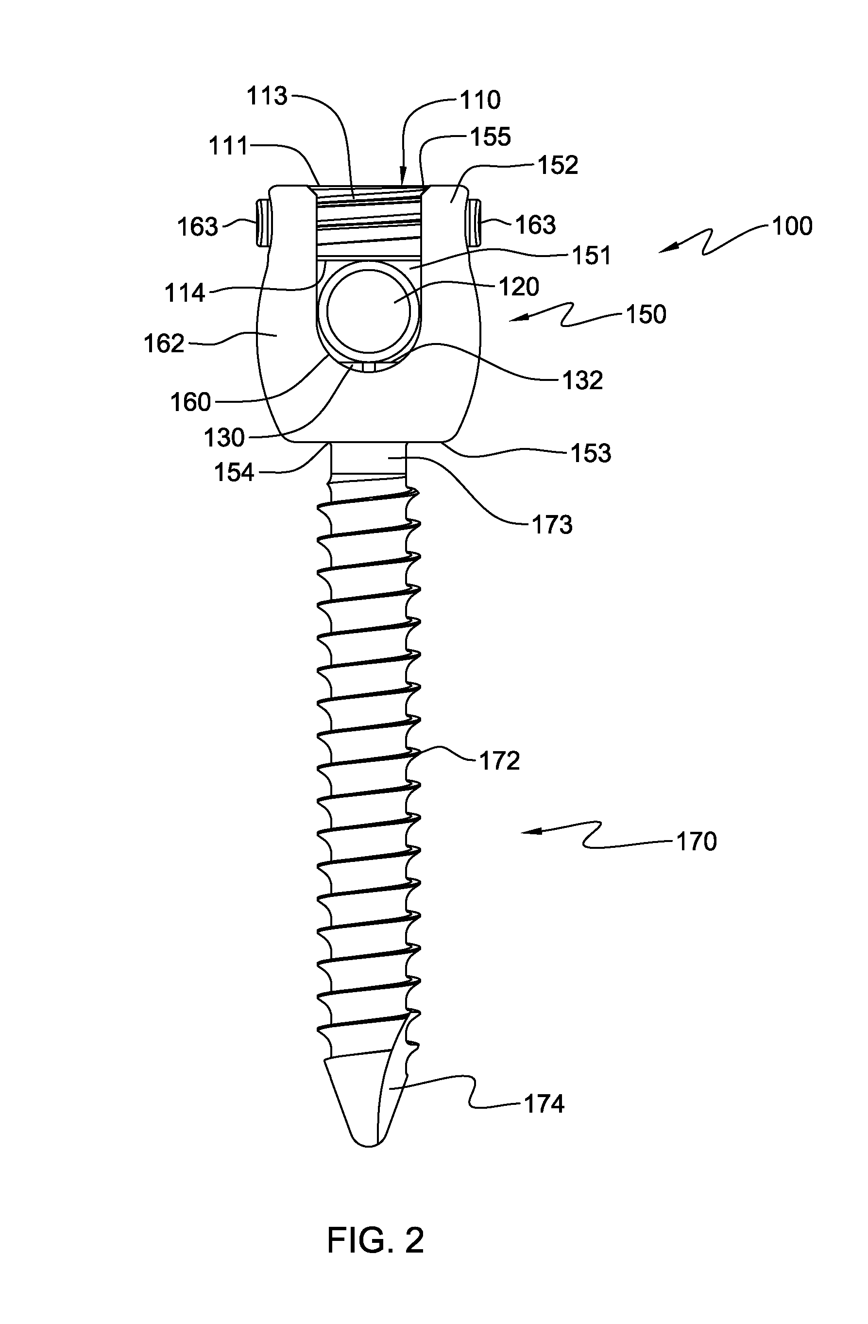
[0029]For the purposes of promoting an understanding of the principles of the pedicle screw assembly, reference will now be made to the embodiments, or examples, illustrated in the drawings that have been attached hereto and specific language will be used to describe these. It will nevertheless be understood that no limitation of the scope of the invention is thereby intended. Any alterations and further modifications in the described embodiments, and any further applications of the principles of the invention as described herein are contemplated as would normally occur to one skilled in the art to which the pedicle screw assembly invention relates.

[0030]In this detailed description and the following claims, the words proximal, distal, anterior, posterior, medial, lateral, superior and inferior are defined by their standard usage for indicating a particular part of a surgical implant according to the relative disposition of the surgical implant or directional terms of reference. For...


PUM

PropertyMeasurementUnit
Forceaaaaaaaaaa
Shapeaaaaaaaaaa
Circumferenceaaaaaaaaaa

Abstract

A pedicle screw assembly and method of assembly are disclosed. The pedicle screw assembly includes a bone fastener having a head at a proximal end and a threaded portion extending between the proximal end and a distal end. The assembly also includes a compression member having a conical inner surface and a locking member having an outer surface adapted to mate with the conical inner surface of the compression member. The assembly may also have an elongated member and a set screw that has a threaded portion. The assembly may also have a receiving housing having a central bore extending from a threaded proximal end to a distal end and a U-shaped cavity positioned perpendicular to the central bore and configured to receive the elongated member.

Description

CROSS REFERENCE TO RELATED APPLICATION[0001]This application is related and claims priority to U.S. provisional patent application number 61 / 390,000 filed on Oct. 5, 2010, the entirety of which is hereby incorporated by reference.TECHNICAL FIELD[0002]This invention relates generally to the field of surgical implants, and more specifically, to the field of spine fixation devices and assemblies.BACKGROUND OF THE INVENTION[0003]Spinal fixation assemblies may be used to align and / or fix a desired relationship between adjacent vertebrae. Such assemblies generally include a connecting rod that is attached to a plurality of vertebral bodies by an anchoring device which may include hooks, bolts, wires, or screws. The connecting rod can have a predetermined shape or contour that has been designed according to the properties of the target implantation site, and once installed, the rod secures the plurality of vertebral bodies in a specific spatial relationship to allow bone fusion to occur.[0...

Claims


Application Information

Patent Timeline
IPC IPC(8): A61B17/86
CPCA61B17/7032A61B17/7037A61B17/866A61B17/8605
Inventor SAVAGE, DANIEL S.
Owner SKELETAL DESIGN PARTNERSHIP LLC
Why Eureka
Try Eureka