Calibration method, calibration device and measurement device

Active Publication Date: 2013-08-15
NXP BV
View PDF14 Cites 75 Cited by
  • Summary
  • Abstract
  • Description
  • Claims
  • Application Information

AI Technical Summary

Benefits of technology

[0009]It is an object of the invention to reduce calibration efforts of the kind set forth to single and relatively simple end-user actions. This is achieved by a metho

Problems solved by technology

The former need may be caused by tolerances in the fabrication process of sensor, signal conditioning circuitry and/or signal conversion circuitry and the latter may be caused by lifetime aging of these components.
Unfortunately, the calibration of a measurement device may be time-consuming and error prone.
When thousands of measurement

Method used


Image

  • Calibration method, calibration device and measurement device
  • Calibration method, calibration device and measurement device
  • Calibration method, calibration device and measurement device

Examples


Embodiment Construction

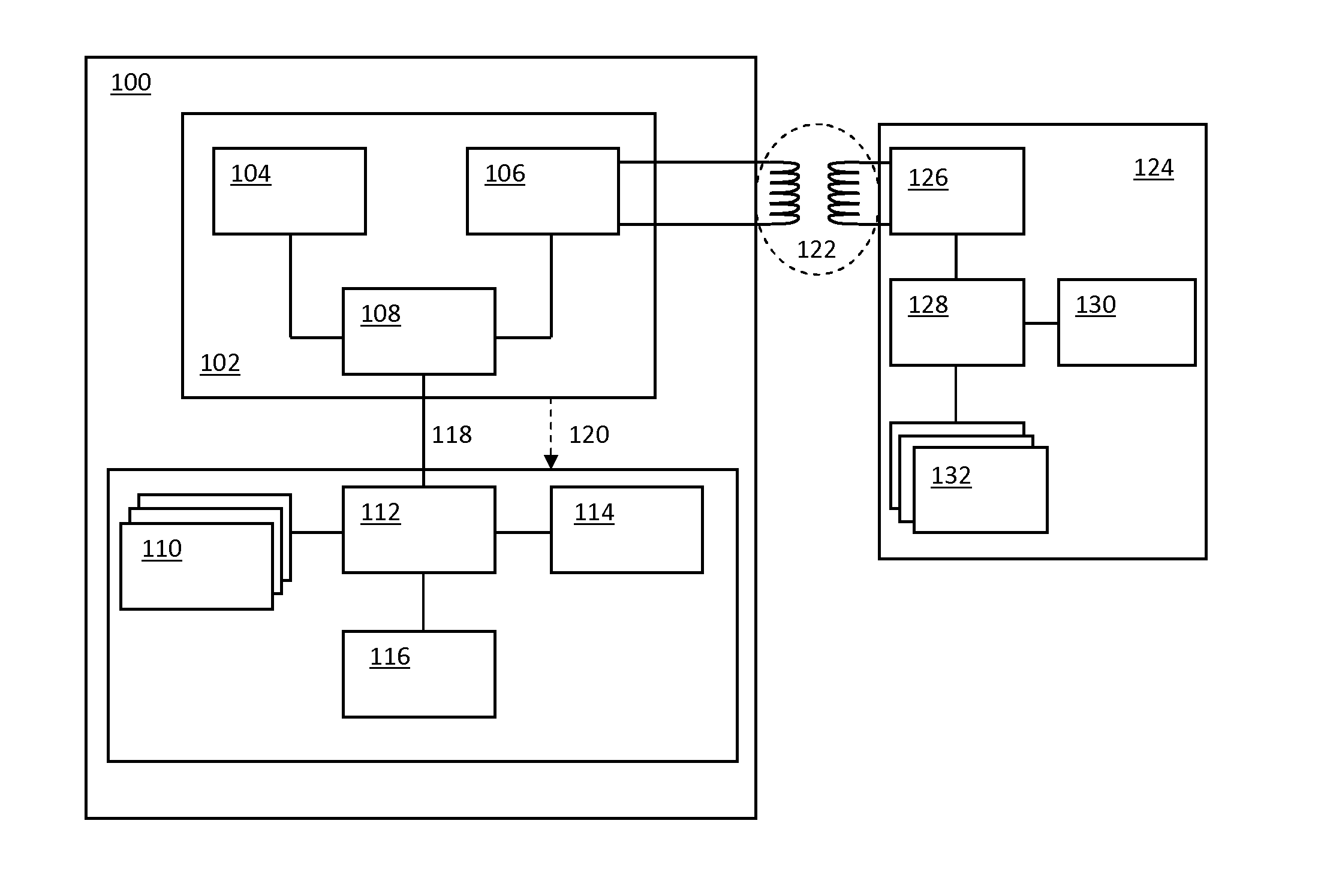
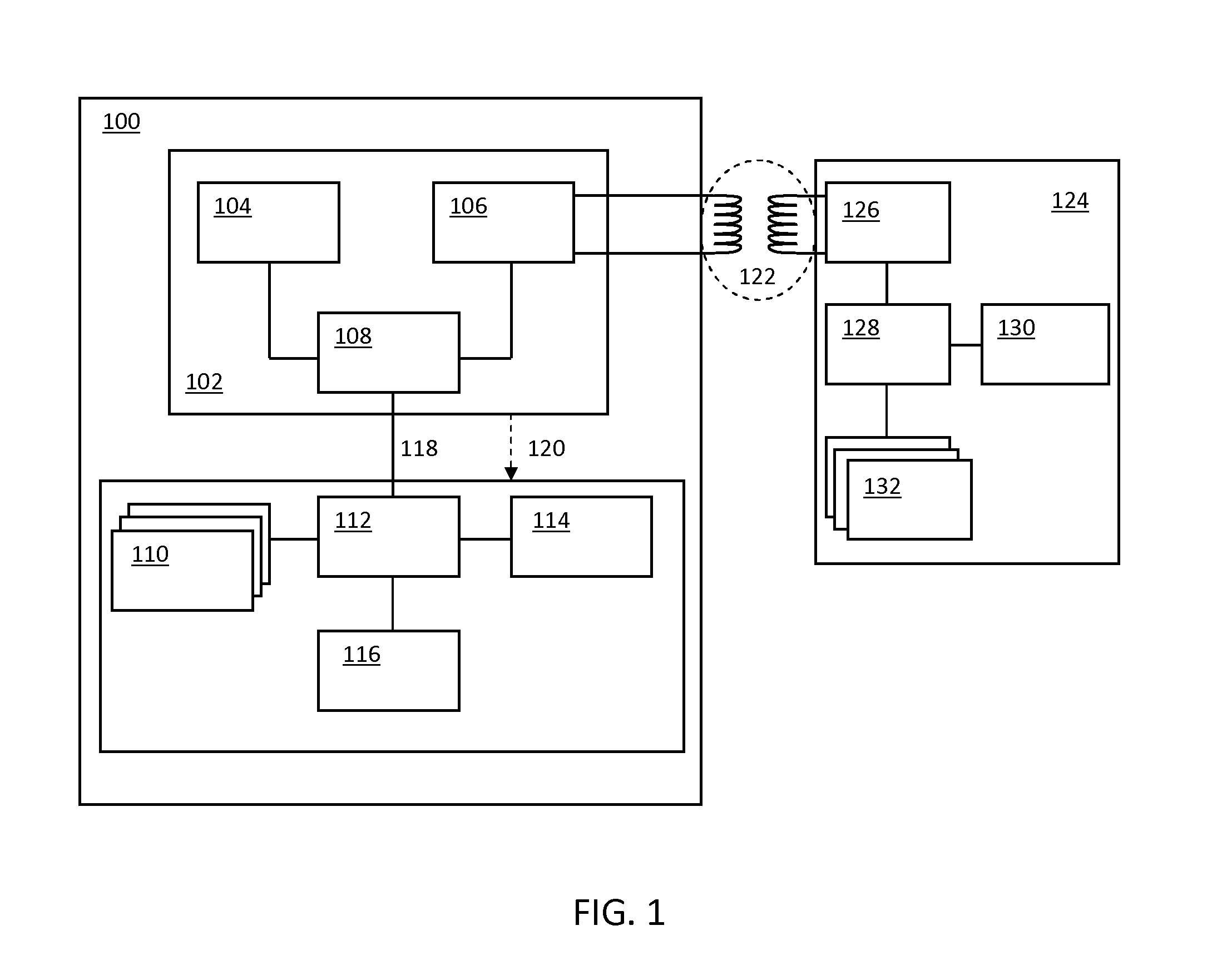
[0032]FIG. 1 illustrates a system wherein an exemplary embodiment of the calibration method according to the invention is used.

[0033]According to an exemplary embodiment of the invention the method for calibrating a measurement device by means of a calibration device comprises the following steps:[0034]1. A user brings the calibration device and the measurement device in close proximity of each other.[0035]2. A data communication link is established between the calibration device and the measurement device when they are in close proximity of each other. For example, such a close-proximity data communication link may be enforced by means of near-field communication, as will be explained in detail below.[0036]3. The calibration device—comprising at least one sensor—performs a measurement of at least one physical phenomenon pertaining to its environment and sends the results of this measurement to the measurement device via the data communication link.[0037]4. The measurement device—co...


PUM


Abstract

According to an aspect of the invention a method for calibrating a measurement device is conceived wherein: a calibration device is brought into close proximity of the measurement device such that a data communication link is established between the measurement device and the calibration device; wherein the following steps are performed while the calibration device and the measurement device are in close proximity of each other: the calibration device performs a measurement of at least one physical phenomenon; the measurement device performs a measurement of the same physical phenomenon; the result of the measurement by the measurement device is compared with the result of the measurement by the calibration device; and calibration parameters are computed based on a difference between the result of the measurement by the measurement device and the result of the measurement by the calibration device.

Description

FIELD OF THE INVENTION[0001]The invention relates to a method for calibrating a measurement device. The invention also relates to a computer program product, a calibration device and a measurement device.BACKGROUND OF THE INVENTION[0002]Electronic measurement devices typically comprise one or more sensors which are arranged to sense at least one physical phenomenon. This physical phenomenon may be a voltage, a current, a temperature, a humidity-level, a CO2-level, a pH-value, and atmospheric pressure, for example. Besides the sensors electronic measurement devices typically comprise signal conditioning, conversion and processing circuitry. In addition, the measurement devices comprise interfaces for conveying the results of measurements of physical phenomena to a user. These interfaces may consist of a display or a wired or wireless communication link. The user could, for example, be a person or an autonomous control or monitoring system controlling or monitoring the physical phenom...

Claims


Application Information

Patent Timeline
IPC IPC(8): G01D18/00G06F17/00
CPCG01D18/00G06F17/00G05B19/0423G05B2219/2642G05B2219/21065G05B2219/25286G05B2219/21064G01D21/00
Inventor BRANDSMA, EWOUTPENNINGS, MAARTEN CHRISTIAANSYED, ALY AAMERVAN ROERMUND, TIMO
Owner NXP BV
Why Eureka
Try Eureka