Linear actuator for actuating a mechanical unit, preferably for actuating a clutch

A technology of linear actuators and clutches, applied in the direction of non-mechanical drive clutches, clutches, fluid-driven clutches, etc., to achieve the effect of simplifying the installation process, realizing free movement in the radial direction, and simple installation steps

Active Publication Date: 2017-02-15
SCHAEFFLER TECH AG & CO KG
View PDF13 Cites 0 Cited by
  • Summary
  • Abstract
  • Description
  • Claims
  • Application Information

AI Technical Summary

Problems solved by technology

This means: There is no unambiguously associable force introduction or force output of the actuating element, which would lead to: Radial forces due to overdetermined bearings

Method used


Image

  • Linear actuator for actuating a mechanical unit, preferably for actuating a clutch

Examples


Embodiment Construction

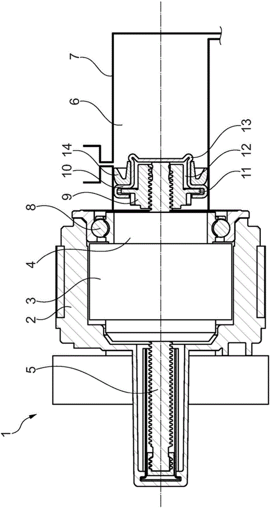
[0017] exist figure 1 shows a linear actuator, which is used, for example, to actuate a clutch in a vehicle.

[0018] The linear actuator 1 includes a stator 2, and a rotor 3 is arranged inside the stator, wherein the stator 2 and the rotor 3 constitute a motor. The rotor 3 surrounds a rotary-linear drive 4 , which is designed, for example, as a planetary roller screw drive. Via this transmission 4 , the rotational movement of the electric motors 2 , 3 is transmitted to a threaded spindle 5 , which executes an axial translational movement. The threaded spindle 5 is surrounded by a pressure chamber 6 formed by a housing unit 7 , for example a master cylinder. The rotor 3 is supported on the transmission 4 via a rotor bearing 8 .

[0019] A device serving as a piston is arranged on the side of the threaded spindle 5 facing the pressure chamber 6 . The device consists of a seal carrier 9 which is fixedly positioned rotationally symmetrically on the threaded spindle 5 . On th...


PUM


Abstract

The invention relates to a linear actuator for actuating a mechanical unit, preferably for actuating a clutch, comprising an electric motor (2, 3) which is connected to a transmission system (4) which is designed to convert the rotary movement of the electric motor (2, 3) into the translational movement of an actuating element (5). The actuating element (5) is sealed by a sealing element (14) against a pressure chamber (6) which is formed by a housing unit (7). In the case of a linear actuator in which there is no need to overstate the bearing of the sealing element, the sealing element (14) radially surrounds a sealing bearing element (9) which is rigidly connected to the axially-movable actuating element (5), and the sealing element (14) is arranged to be radially freely displaceable .

Description

technical field [0001] The invention relates to a linear actuator for actuating a mechanical unit, preferably for actuating a clutch, said linear actuator comprising an electric motor connected to a transmission system configured to convert the rotation of said electric motor The movement is converted into a translational movement of the actuating element, wherein the actuating element is sealed off from the pressure chamber formed by the housing unit via the sealing element. Background technique [0002] In clutch actuation systems, electronics are used which have an electric motor for the drive and a rotary linear drive for converting the rotary motion of the electric motor into a linear motion for actuating the clutch. The linear actuator here includes a transmission system which is connected to the rotor of the electric motor. In such linear actuators, for example electromechanical hydrostatic actuators, the transmission system has a screw which moves the piston in a pr...

Claims


Application Information

Patent Timeline
Patent Type & Authority Applications(China)
IPC IPC(8): F16J15/3232F16J15/3252F16H25/24
CPCF16H25/2418F16J15/00F16J15/3232F15B7/08F15B15/1452F16D25/08F16D2025/081F16H25/20F16H25/2252F16H2025/2075F16J15/32
Inventor 热罗姆·马利图尔内拉斯洛·曼彼得·格雷布
Owner SCHAEFFLER TECH AG & CO KG
Why Eureka
Try Eureka