Rubber crawler track

a crawler track and rubber technology, applied in the direction of driving belts, belts/chains/gearrings, mechanical instruments, etc., can solve the problems of large cracks in the circumferential direction of the rubber crawler track main body, inability to prevent the rise of costs, and broken rubber elastic bodies, so as to prevent the phenomenon of migrating effectively and economically.

Inactive Publication Date: 2006-03-23
FUKUYAMA GOMU IND FUKUYAMA GAISHA
View PDF1 Cites 26 Cited by
  • Summary
  • Abstract
  • Description
  • Claims
  • Application Information

AI Technical Summary

Benefits of technology

[0012] The present invention aims to settle the above-mentioned problems and to provide ...

Problems solved by technology

Therefore, the rubber elastic body is broken.
Whenever such a state is repeated, destruction of the rubber elastic body progresses, thereby finally causing a large crack in the circumferential direction in the rubber crawler track main body.
However, in the above-mentioned inventions, the cost can not be prevented fr...

Method used


Image

  • Rubber crawler track
  • Rubber crawler track
  • Rubber crawler track

Examples


first embodiment

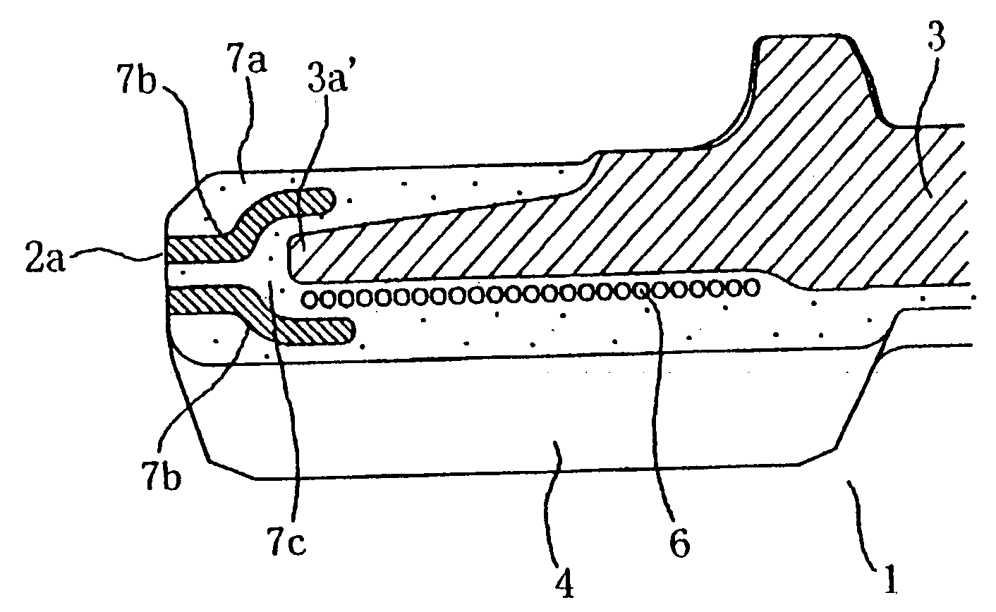
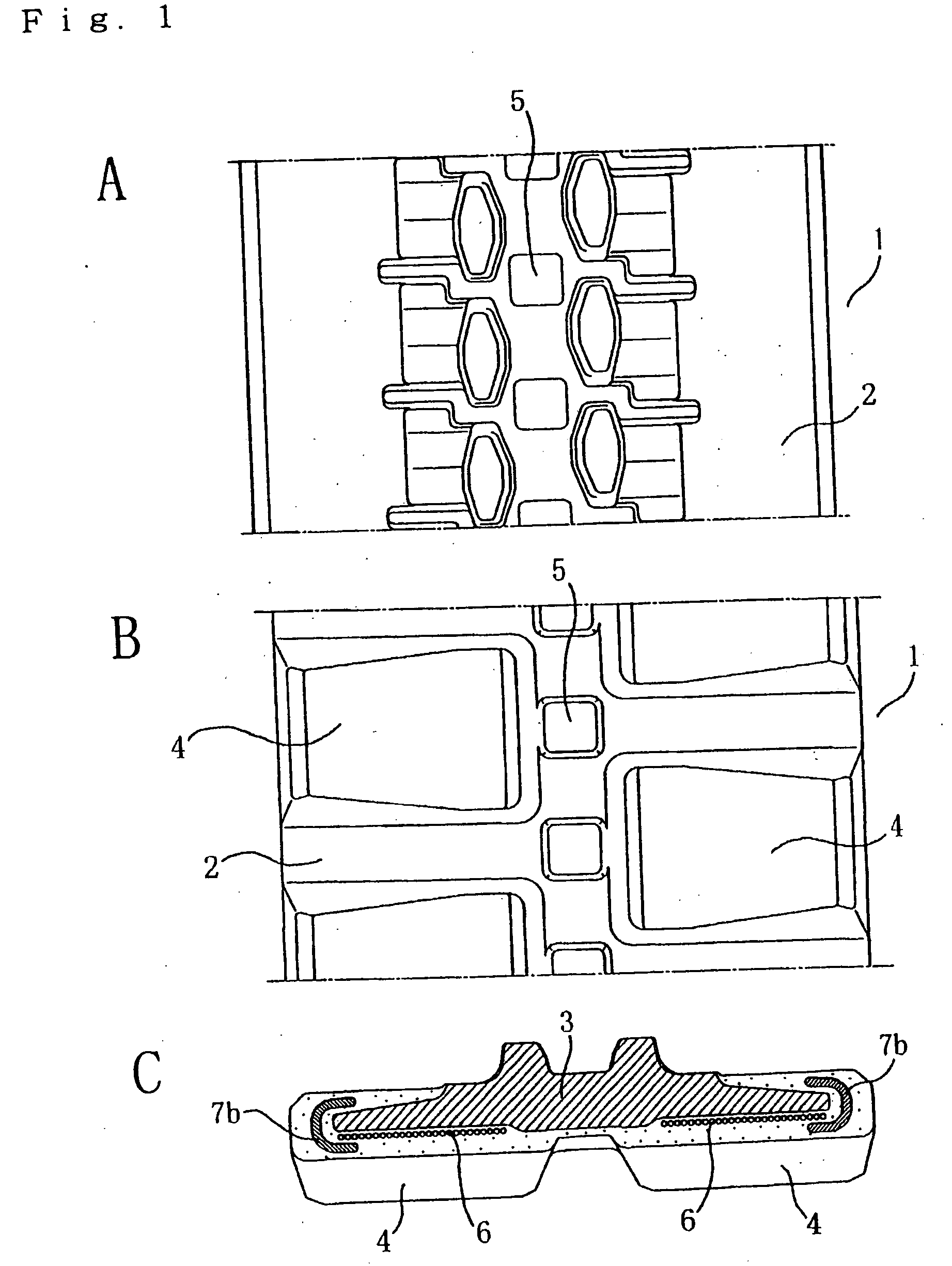
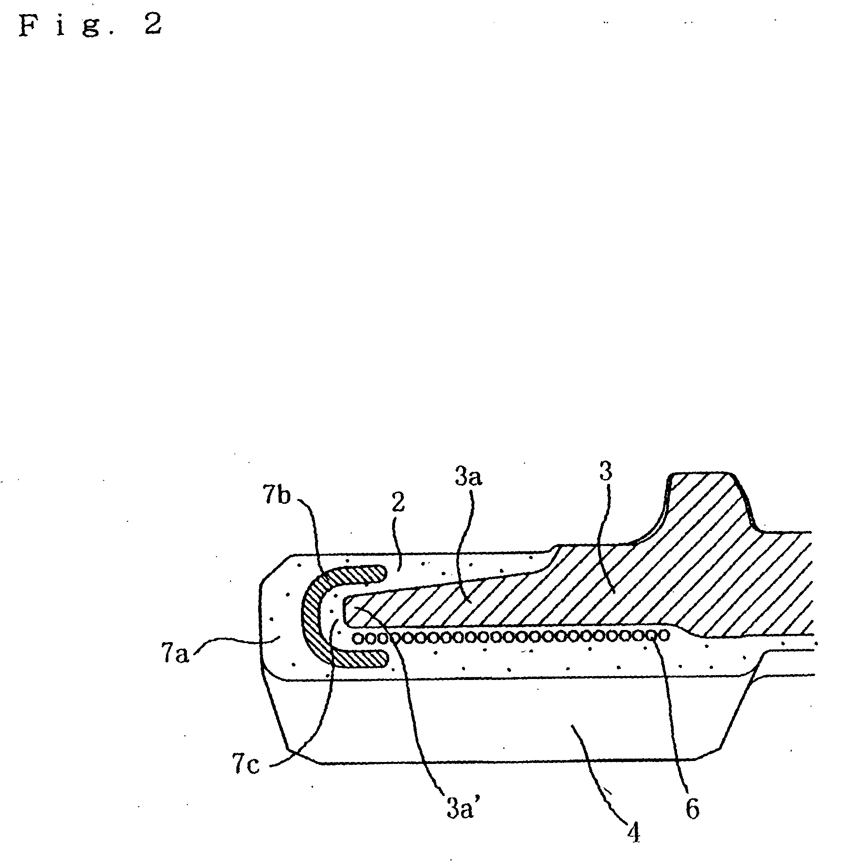
[0040]FIG. 1A is a plan view of the inside circumferential side (ground not-contacting surface side) of a rubber crawler track of the present invention. FIG. 1B is a plan view of the outside circumferential side (ground contacting surface side). FIG. 1C is a sectional view in a width direction of FIG. 1B. FIG. 2 is an enlarged view of an important part of FIG. 1C.

[0041] A rubber crawler track 1 of the first embodiment comprises an endless rubber belt-shaped rubber crawler track main body 2 formed of a rubber elastic body, etc. and core metal pieces 3 embedded therein at predetermined intervals in a circumferential direction. Rubber lugs 4 are protrusively formed on the ground contacting surface side of the rubber crawler track 1. Steel cord rows 6 are embedded on the outside circumferential side of the core metal pieces 3 along the circumferential direction of the rubber crawler track so as to be divided to the left and right of engaging holes 5 that interlock with a driving wheel o...

third embodiment

[0056]FIG. 7 is an enlarged sectional view of an important part of a rubber crawler track of a

[0057] Core metal pieces 3 embedded in the rubber crawler track 1 of the third embodiment are so constructed that each has an inclination 3b formed on the crawler track ground contacting surface side of the end portion 3a′ in FIG. 6 of the second embodiment.

second embodiment

[0058] In this embodiment, the intermediate rubber layer formed of the high hardness rubber elastic body does not lie within the rubber crawler track main body. Although the effect for MIMIGIRE prevention is inferior to that of the second embodiment, an equal effect can be gained according to the above-mentioned core metal pieces. Even if the rubber crawler track 1 runs aground on the stones or the curbs, strain is not concentrated on a part of the rubber elastic body put between the end portion 3a′ and them, and is effectively dispersed and lightened by the core metal piece shape. Therefore, a rubber elastic body in this portion is not destroyed and the rubber crawler track can prevent a crack from occurring, thereby preventing MIMIGIRE from occurring in the rubber crawler track.


PUM


Abstract

A rubber crawler track (1) has an endless rubber belt-shaped rubber crawler track main body (2) formed of a rubber elastic body, etc. and core metal pieces (3) embedded in the rubber crawler track main body (2) at predetermined intervals in a circumferential direction of the rubber crawler track, wherein a high hardness intermediate rubber layer track main body (2) is provided from below at least the ground contacting surface side of an end portion in a length direction (rubber crawler track width direction) of the core metal pieces (3) toward outside the end portion in a width direction of the rubber crawler track. The rubber elastic body of the rubber crawler track main body (2) is formed in a multiply layered structure with at least two or more layers.

Description

TECHNICAL FIELD [0001] The present invention relates to a rubber crawler track mounted on an endless track traveling device for farm working machines, construction machines, engineering work machines, and industrial vehicles such as transportation vehicles. Particularly, the present invention prevents MIMIGIRE phenomenon in an end portion in a width direction of a rubber crawler track from occurring. TECHNICAL BACKGROUND [0002] Although an iron crawler track has been conventionally used as an endless track traveling device for mobile construction machine vehicles and so on, it has recently come to be used in work on pavement in town areas. Therefore, a link-type rubber crawler track or an integral rubber crawler track is used with the iron crawler track. Here, the link-type rubber crawler track is so constructed that backing shoes having rubber elastic bodies are integrally cured and bound on metallic shoe plates instead of the iron crawler track, or rubber pads having rubber elasti...

Claims


Application Information

Patent Timeline
IPC IPC(8): B62D55/24B62D55/253
CPCB62D55/244
Inventor UCHIYAMA, TSUYOSHI
Owner FUKUYAMA GOMU IND FUKUYAMA GAISHA
Why Eureka
Try Eureka