Dynamic fluid valve and method for establishing the same

a technology of dynamic fluid valve and fluid valve, which is applied in the direction of ion implantation coating, chemical vapor deposition coating, coating, etc., can solve the problems of air lock and the like, affecting the operation speed of the air lock, and affecting the quality of the air. the effect of the valv

Active Publication Date: 2013-02-28
ASM INTERNATIONAL
View PDF6 Cites 25 Cited by
  • Summary
  • Abstract
  • Description
  • Claims
  • Application Information

AI Technical Summary

Benefits of technology

[0016]The passage forms an open connection between the exterior and the process space. Consequently, a flow of exchange fluid traveling through the passage and having sufficient momentum might be forced into the exterior or the process space—whichever of the two has the atmosphere of the highest pressure and thus defines the target direction of the fluid flow—before it comes to rest or stagnates. If the flow of exchange fluid would stagnate in the exterior atmosphere or the process space atmosphere, the exchange fluid would subsequently diffuse therein. Although this need not be an issue, it may be desirable to keep the exchange fluid substantially separated from the exterior atmosphere and / or the process space atmosphere. This may be effected by designating a portion of the passage as a stagnation region, and providing this portion with an exchange fluid discharge channel. During operation, the stagnation region may form the location just upstream of the point where the exchange fluid flow encounters the atmosphere of the highest pressure, and at least partially stagnates. To prevent accumulation of exchange fluid in the stagnation region (which would be accompanied by an upstream retreat of the point where stagnation takes place), the exchange fluid discharge channel is provided. This channel is configured to discharge the exchange fluid from the stagnation region to a suitable location.
[0018]The exchange fluid may thus be circulated: after the exchange fluid injection means inject the exchange fluid into the passage, the exchange fluid flows to the stagnation region where it stagnates, and from where it is subsequently discharged via the exchange fluid discharge channel back to the exchange fluid injection means. In some embodiments of the invention, in particular those employing air as the exchange fluid, the circulation path of the exchange fluid may include the exterior atmosphere. The exchange fluid discharge channel may for example be in open communication with the exterior and be configured to discharge exchange fluid from the stagnation region to the exterior, while the exchange fluid injection means may be configured to withdraw exchange fluid from the exterior. Such an air-based embodiment obviates the need for an accurately sealed circulation path along which a selected exchange fluid may be transported.
[0020]The location at which stagnation of the flow of exchange fluid occurs may be determined by selecting the flow rate at which exchange fluid is injected into the passage. Generally, a higher injection flow rate will effect a further downstream stagnation location. The flow rate may be chosen such that stagnation of the flow of exchange fluid occurs in the stagnation region. In that case, the pressure in the stagnation region will settle at a stagnation pressure that is substantially equal to the greater one of the exterior atmosphere pressure and the process space pressure. This allows the stagnation region to serve as a dynamic fluid valve that closes off the passage from the higher pressure atmosphere.
[0022]Such a selection of static and dynamic pressure may ensure a dynamic equilibrium in the passage, which equilibrium may enable optimal separation between the exchange fluid flow and the exterior and process space atmospheres. At the injection point, the static pressure may prevail and the pressure in the exchange fluid may be substantially equal to the pressure of the lower pressure atmosphere. There where the fluid flow stagnates, the kinetic potential of the flow may be transformed into a thermodynamic pressure so as to yield a stagnation pressure that is substantially equal to the higher pressure atmosphere. Accordingly, the pressure differential across the passage may be balanced by the exchange fluid flow in the passage, which renders the passage effectively unaccessible to fluids from the adjacent atmospheres.
[0024]As the passage serves to exchange substrates, some of which may be fragile, the flow regime inside the passage may preferably be laminar (as opposed to turbulent). In addition, the flow of exchange fluid may preferably extend in a direction parallel to the passage direction, i.e. the direction along which substrates are transported through the passage, so as to prevent unbalanced flow components from straining the substrate and / or pushing it towards or against the bounding walls of the passage.

Problems solved by technology

Such a flow of atmospheric fluid may lead to contamination of the receiving atmosphere and to possible depletion of the supplying atmosphere.
However, air locks and the like have the drawback that they operate relatively slowly.
As a result, the use of air locks may be accompanied by a detrimental effect on the through-put capacity of an apparatus.
That is to say, the air lock may limit the rate at which substrates may be inserted into or extracted from the process space.

Method used


Image

  • Dynamic fluid valve and method for establishing the same
  • Dynamic fluid valve and method for establishing the same
  • Dynamic fluid valve and method for establishing the same

Examples


Embodiment Construction

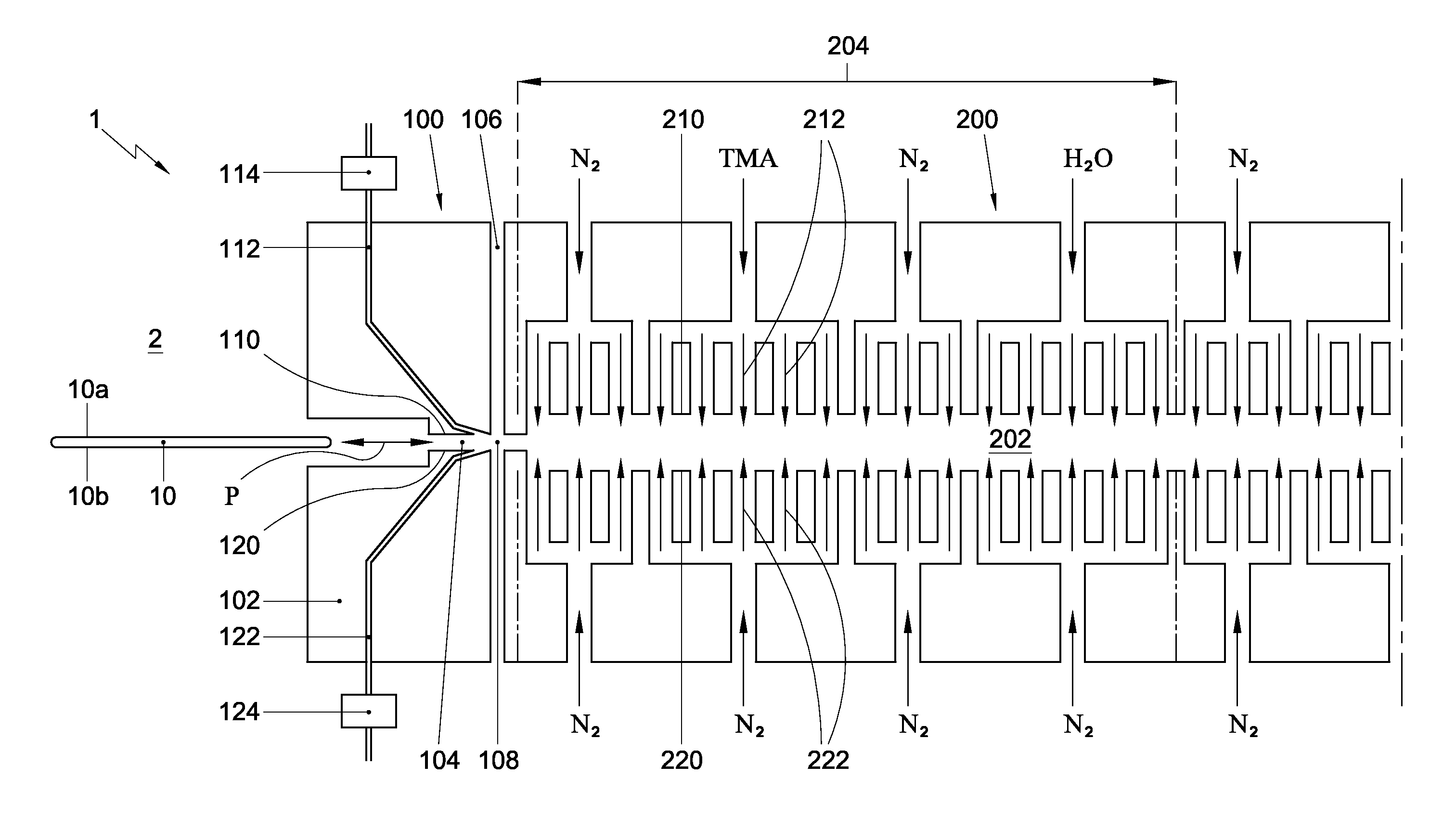
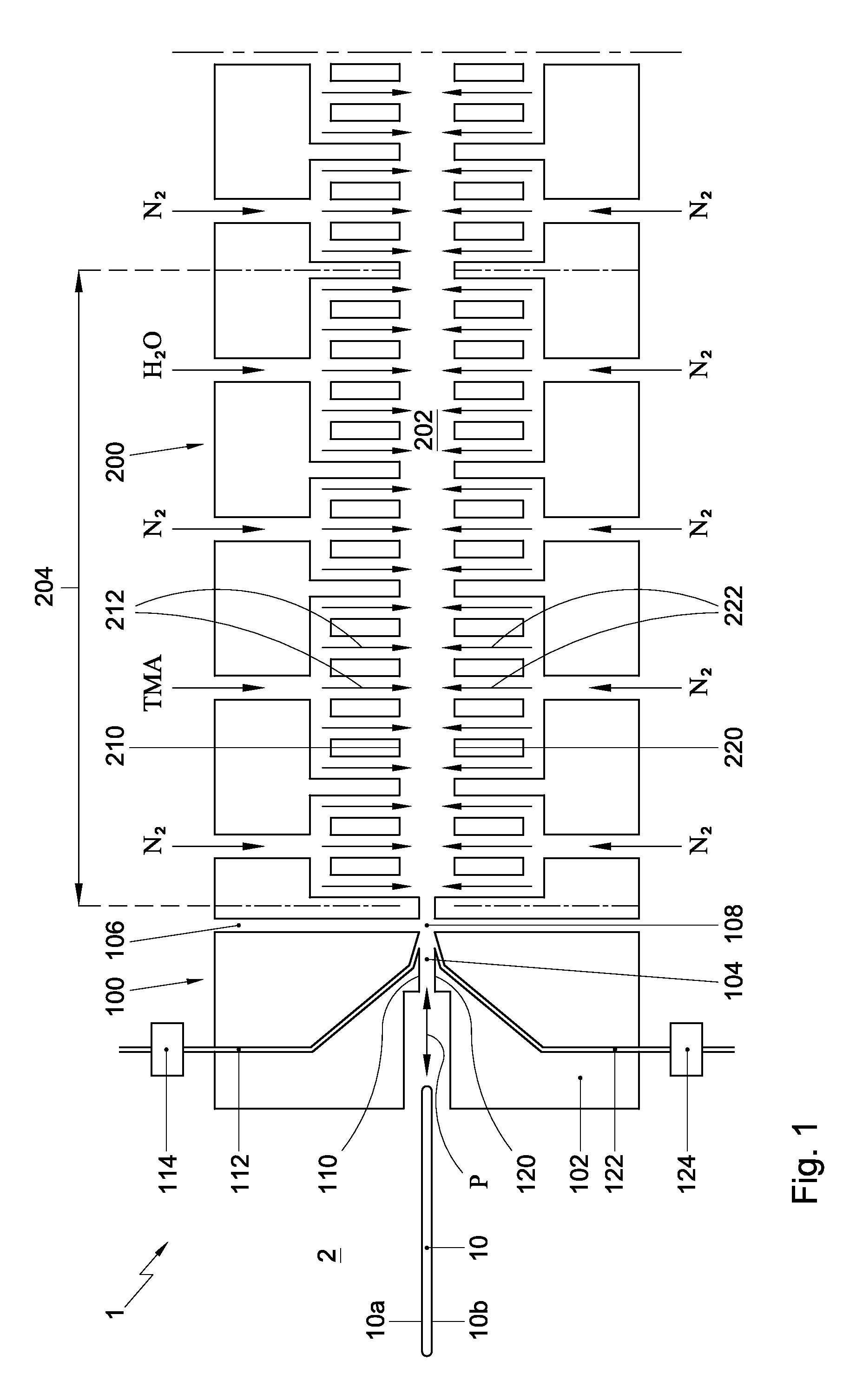
[0029]The construction of the apparatus according to the present invention will be described below in general terms. In doing so, reference will be made to the exemplary embodiment shown in FIG. 1, which is set up as a spatial atomic layer deposition (ALD) apparatus 1 for processing floatingly supported semi-conductor substrates 10. FIG. 1 is a diagrammatic longitudinal cross-sectional view of a portion of the exemplary ALD apparatus 1, comprising an exchange section 100 and a process tunnel 200 that is connected thereto.

[0030]The exchange section 100 may comprise a body 102. The body 102 may define at least a portion of a passage 104, via which an exterior 2 of the apparatus 1 is in open communication with a process space 202, and through which a substrate 10, e.g. a silicon wafer, is exchangeable between the exterior 2 and the process space 202. The passage 104 may extend in a passage direction P. The portion of the passage 104 defined by the body 102 of the exchange section 100 m...


PUM

PropertyMeasurementUnit
thicknessaaaaaaaaaa
thicknessaaaaaaaaaa
widthaaaaaaaaaa

Abstract

A method, comprising: —providing a process space atmosphere at a process space atmosphere pressure; —providing an exterior atmosphere at an exterior atmosphere pressure that is different from the process space atmosphere pressure; —providing a passage via which the exterior atmosphere is in open communication with the process space atmosphere, and via which substrates are exchangeable between the exterior atmosphere and the process space atmosphere; —injecting an exchange fluid into the passage at at least one exchange fluid injection point, so as to effect a flow of exchange fluid that extends through at least a part of the passage, wherein said flow is directed towards—the exterior in case the exterior atmosphere pressure is greater than the process space atmosphere pressure; or—the process space in case the exterior atmosphere pressure is smaller than the process space atmosphere pressure.

Description

FIELD OF THE INVENTION[0001]The present invention relates to the field of substrate processing, and, more particularly, to an apparatus and method for establishing a fluid valve for separating a process space atmosphere from an exterior atmosphere while allowing substrates to be exchanged therebetween.BACKGROUND[0002]A substrate processing apparatus may include a process space that, during operation, holds a gaseous atmosphere into and from which substrates may be inserted and extracted, respectively. The process space atmosphere may typically have characteristics that are different from those of an exterior atmosphere of the apparatus. The process space atmosphere may for example differ from the exterior atmosphere in chemical composition, temperature and / or pressure.[0003]In case a process space atmosphere is maintained at a pressure that differs from that of the exterior atmosphere, any open connection between them is subject to a pressure differential that tends to drive atmosph...

Claims


Application Information

Patent Timeline
Patent Type & Authority Applications(United States)
IPC IPC(8): C23C16/455
CPCC23C14/568H01L21/67784C23C16/45551H01L21/67109H01L21/67276
Inventor KUZNETSOV, VALDIMIRTAK, PIETER
Owner ASM INTERNATIONAL
Why Eureka
Try Eureka