Method and control devices for production of consistent water quality from membrane-based water treatment for use in improved hydrocarbon recovery operations

a technology of water treatment and control devices, which is applied in the direction of treatment water, membranes, borehole/well accessories, etc., can solve the problems of reducing the permeability of the reservoir, reducing the amount or quality of the hydrocarbon product produced from the production wells, and difficulty in some locations in disposing of produced water offshor

Active Publication Date: 2013-08-22
CLEAN H2O TECH LLC
View PDF4 Cites 60 Cited by
  • Summary
  • Abstract
  • Description
  • Claims
  • Application Information

AI Technical Summary

Benefits of technology

[0019]According to another aspect, there is provided a membrane-based water treatment system, the system including a water intake system that intakes a first amount of water, a plurality of treatment blocks, a produced water reservoir that intakes a second amount of water; and an injection water reservoir or blend point in fluid communication with the plurality of treatment blocks and the produced water reservoir. Each of the plurality of treatment blocks includes at least one pump, a membrane pressure vessel, a monitor, and a controller. The pump feeds the first amount of intake water through the membrane pressure vessel. The membrane pressure vessel comprises at least one membrane element and separates the first amount of intake water into at least an aqueous permeate stream and a concentrate reject stream. The monitor is used to identify different characteristics of each of the aqueous permeate streams, monitor blending of the aqueous permeate streams from two or more treatment blocks, and to monitor the blended aqueous permeate streams from the two or more treatment blocks based on the identified characteristics and predefined water-characteristic tolerances.

Problems solved by technology

Another motivation for using produced water as an injection water offshore is the difficulty in some locations in disposing the produced water offshore.
However, it has also been found that certain ions, including calcium and / or sulfate, present in the injection water may have harmful effects on the injection wells and production wells and can ultimately diminish the amount or quality of the hydrocarbon product produced from the production wells.
The scale reduces the permeability of the reservoir and reduces the diameter of perforations in wellbores, thereby diminishing hydrocarbon recovery from the hydrocarbon production wells.
Reservoir souring is an undesirable phenomenon whereby reservoirs are initially sweet upon discovery, but turn sour during the course of waterflooding and attendant hydrocarbon production from the reservoir.
The hydrogen sulfide gas causes a number of undesired consequences at the hydrocarbon production wells and downstream of the wells, including excessive degradation and corrosion of the hydrocarbon production well metallurgy and associated production equipment, diminished economic value of the produced hydrocarbon fluids, an environmental hazard to the surroundings, and a health hazard to field personnel.
A number of strategies have been employed in the prior art for remediating reservoir souring with limited effectiveness.
However, in addition to the problems associated with sulfate ions being present in the injection water, it has also been found that the salinity of an injection water can have a major impact on the recovery of hydrocarbons during waterfloods, with increased recovery resulting from the use of injection water of lower salinity than natural seawater but sufficient ionic strength to prevent clay instability.
The oil reacts with the clay particles to form organometallic complexes, which results in the clay surface being extremely hydrophobic and oilwet.
This results in increased electrostatic repulsion between the clay particles and the oil.
If, however, the electrolyte content is reduced too much (i.e., the formation fluid salinity is too low), the clay particles may be stripped from the pore walls (clay deflocculation), which will damage the formation.
Lower salinity water, however, is not often available at a well site.

Method used


Image

  • Method and control devices for production of consistent water quality from membrane-based water treatment for use in improved hydrocarbon recovery operations
  • Method and control devices for production of consistent water quality from membrane-based water treatment for use in improved hydrocarbon recovery operations
  • Method and control devices for production of consistent water quality from membrane-based water treatment for use in improved hydrocarbon recovery operations

Examples


example 1

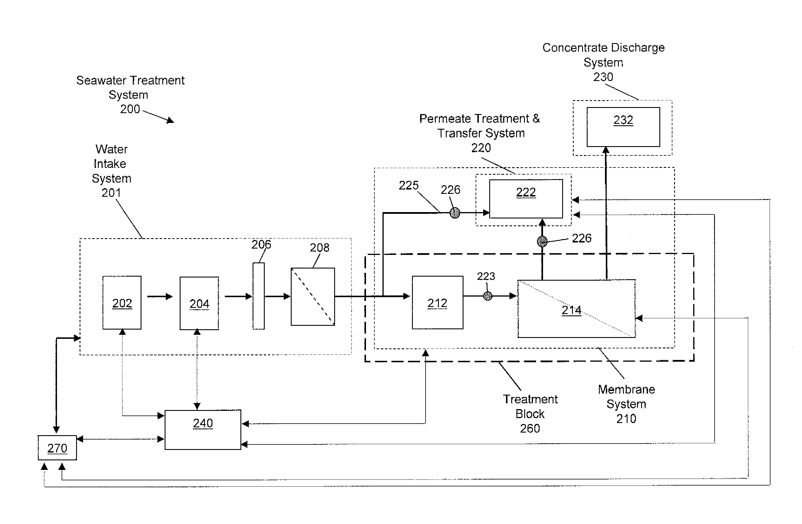
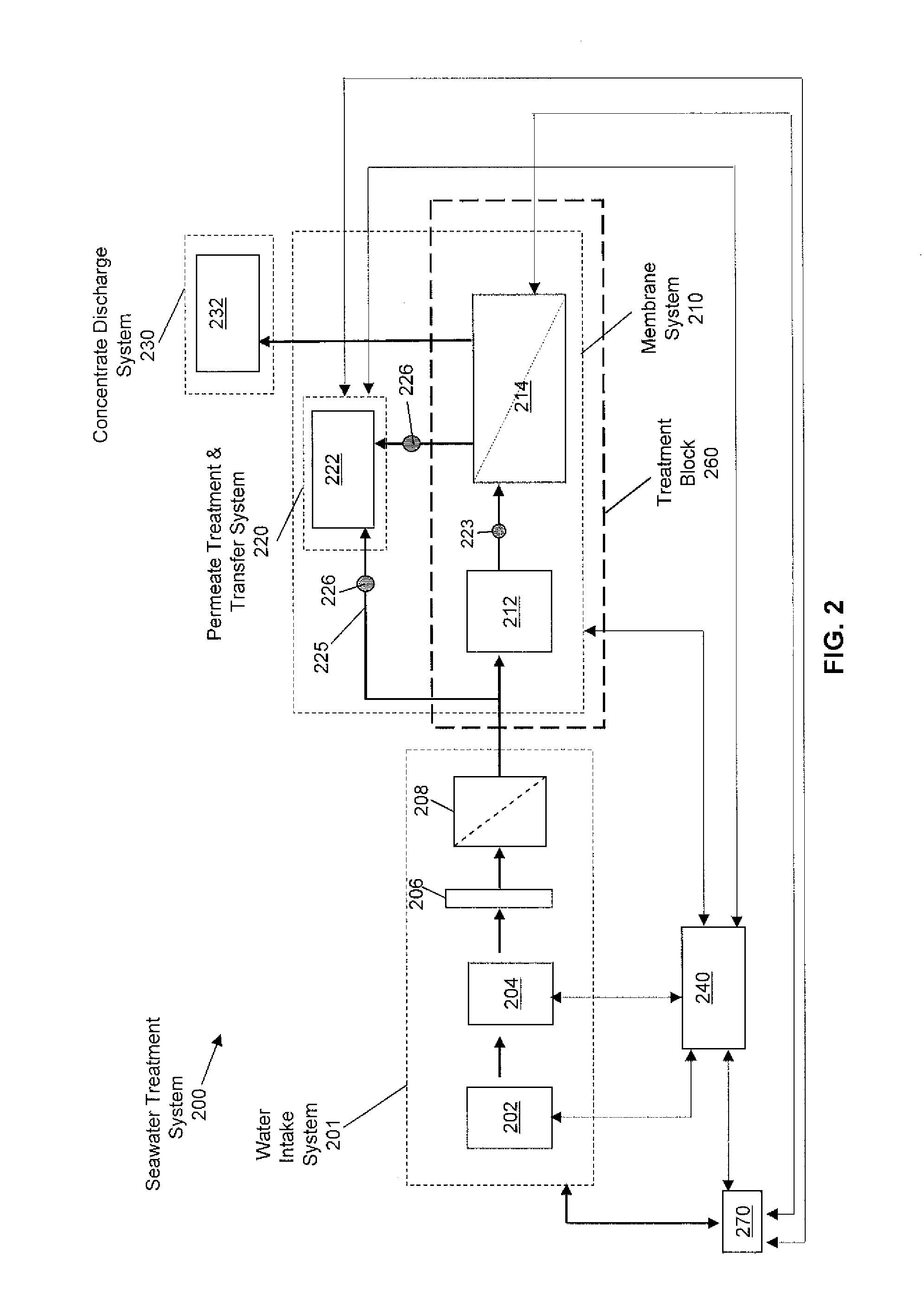
[0112]A system comprised of a treatment block of seawater reverse osmosis membranes and a treatment block of seawater nanofiltration membranes is configured such that the flowrates to each treatment block and the respective high-pressure pump to each block can be regulated. The treatment block is comprised such that it produces approximately 60% of the permeate flow using the nanofiltration block operating at 42% recovery and 40% of the permeate flow using the reverse osmosis block operating at 40% recovery. In this example, the specific (target) salinity (total dissolved solids) of the blended permeate is 2,900 mg / L (+ / −100 mg / L) and the maximum allowable hardness is 60 mg / L (as defined by the combined calcium and hardness ion concentration, in mg / L). The operating range of the system is 25 to 30° C.

[0113]Exhibit 1 provides the natural deviation of the salinity and hardness of a conventional system, comprised of 60% nanofiltration and 40% reverse osmosis, over the temperature range...

example 2

[0117]A system comprised of a treatment block of seawater reverse osmosis membranes and a by-pass stream treatment block of seawater nanofiltration membranes is configured such that the flowrates to each treatment block and the respective high-pressure pump to each block can be regulated. The treatment block is comprised such that it produces approximately 92.8% of the permeate flow using the seawater reverse osmosis membrane block operating at 45% recovery and the remaining permeate flow using a slipstream of permeate from a multi-pass nanofiltration membrane block operating at 75%, 80% and 80% recovery, respectively, for the three-pass system. In this example, the specific (target) salinity (total dissolved solids) of the blended permeate is 2,000 mg / L (+ / −50 mg / L) and the maximum allowable calcium is 10 mg / L, the maximum allowable magnesium is 10 mg / L, and the maximum allowable sulfate is 10 mg / L. The operating range of the system is 22 to 31° C.

[0118]Exhibit 3 provides the natur...


PUM

PropertyMeasurementUnit
concentrationaaaaaaaaaa
diameteraaaaaaaaaa

Abstract

A method for treating water including intaking a first amount of water from a first source into a plurality of treatment blocks, treating the first amount of water, outputting aqueous treated water streams from each of the plurality of treatment blocks, separating the aqueous treated water streams from each of the plurality of treatment blocks into aqueous permeate streams and concentrate reject streams, monitoring each of the aqueous permeate streams, controlling the operation of at least one of the plurality of treatment blocks based on predefined water-characteristic tolerances that fall within a predetermined concentration range based on the different qualities of the aqueous permeate streams, outputting a product water stream into an injection water reservoir or blend point, the product water stream including the aqueous permeate stream, intaking a second amount of water from a second source, treating the second amount of water, and discharging the dischargeable water stream.

Description

BACKGROUND[0001]1. Field of the Invention[0002]Embodiments disclosed herein relate generally to methods and control devices for production of consistent water quality from membrane-based water treatment for use in improved hydrocarbon recovery operations.[0003]2. Background Art[0004]Hydrocarbons accumulated within a subterranean hydrocarbon-bearing formation are recovered or produced therefrom through production wells drilled into the subterranean formation. When production of hydrocarbons slows, improved recovery techniques may be used to force the hydrocarbons out of the formation. One of the simplest methods of forcing the hydrocarbons out of the formation is by direct injection of fluid into the formation. This enhances production by displacing or sweeping hydrocarbons through the formation so that they may be produced from production well(s).[0005]As shown in FIG. 1, a prior art system for recovering hydrocarbons from a formation consists of an offshore rig 12 connected to a we...

Claims


Application Information

Patent Timeline
Patent Type & Authority Applications(United States)
IPC IPC(8): C02F1/44
CPCB01D61/022C02F2209/05B01D61/027B01D61/12B01D63/12B01D2311/04B01D2313/243B01D2313/246B01D2317/04B01D2319/02B01D2319/06B01D61/025C02F2103/365C02F1/44C02F2209/10C02F2209/40C02F2209/055C02F1/441C02F1/442C02F2103/08B01D2311/2649E21B43/20E21B41/005E21B43/08C02F1/008C02F2209/005B01D2311/246B01D61/026
Inventor HENTHORNE, LISA
Owner CLEAN H2O TECH LLC
Why Eureka
Try Eureka