Clamp block assembly

Active Publication Date: 2013-08-22
AIRBUS OPERATIONS LTD
View PDF36 Cites 12 Cited by
  • Summary
  • Abstract
  • Description
  • Claims
  • Application Information

AI Technical Summary

Benefits of technology

[0025]In the clamp block assembly at least two of the clamp blocks may be arranged touching back-to-back. Alternatively, at least two of the clamp blocks may be arranged back-to-back, and the

Problems solved by technology

The existing clamp block assembly design suffers the following disadvantages:No tolerance to any variation in the pipe centre distances (i.e. the distance between the centres of any pair of pipes held within a clamp block), requiring a different clamp block design solution for each distance variation.No tolerance of any variation in the pipe diameters req

Method used


Image

  • Clamp block assembly
  • Clamp block assembly
  • Clamp block assembly

Examples


Example

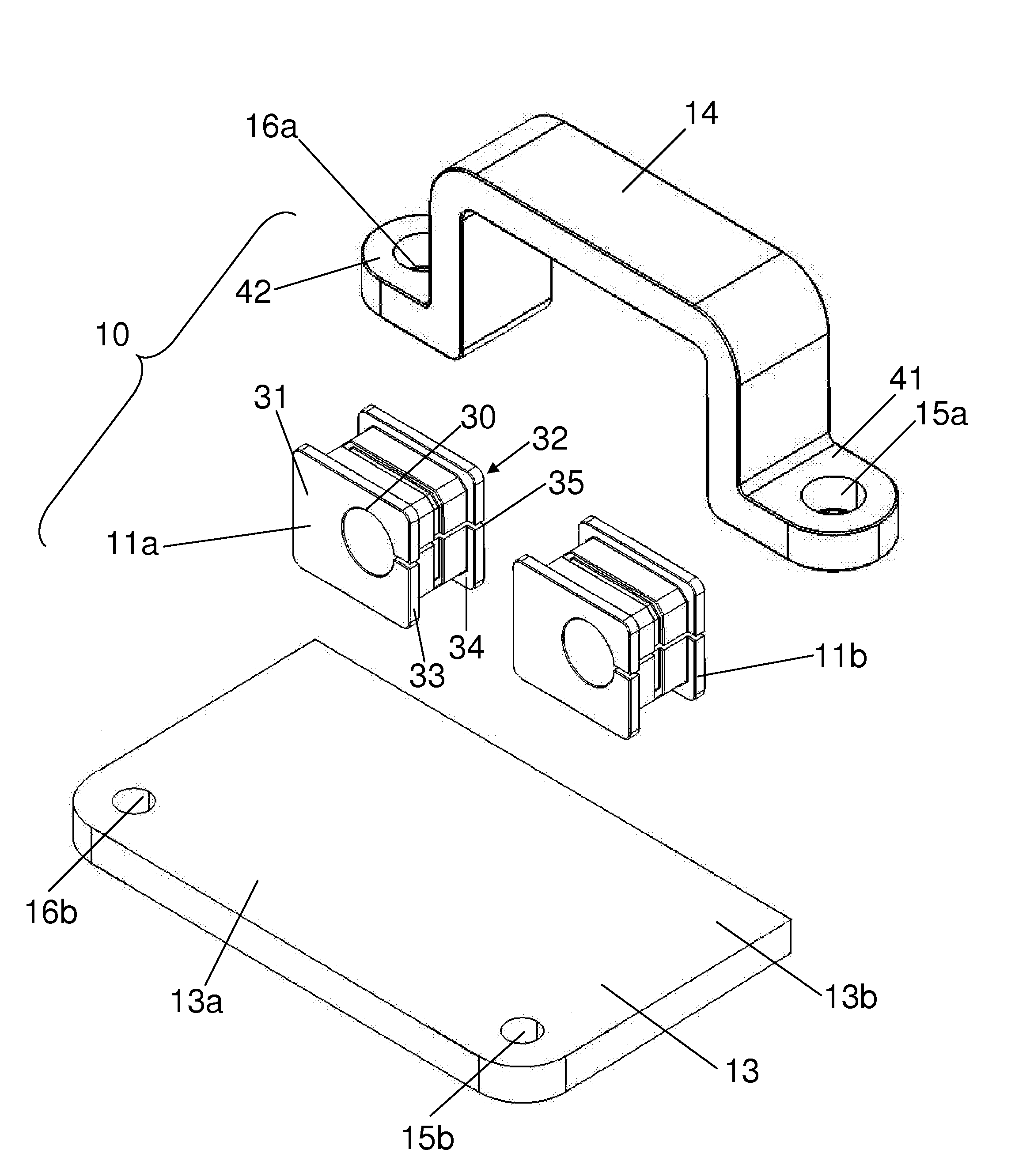
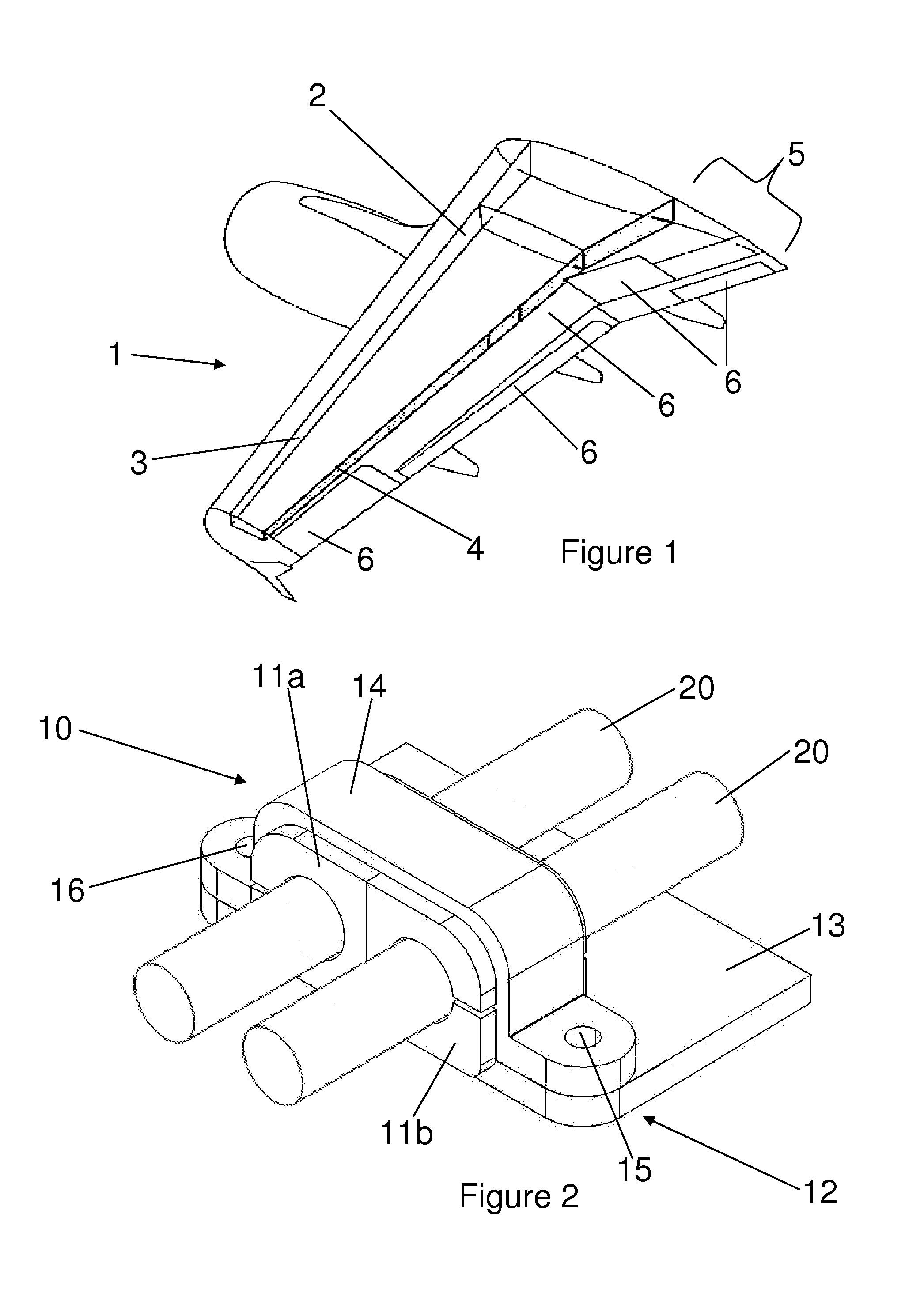
[0038]FIG. 2 illustrates a clamp block assembly 10 in accordance with a first embodiment of the invention used to secure hydraulic pipes 20. The clamp block assembly 10 comprises two discrete unitary clamp blocks 11a, 11b, of deformable material, and a clamp 12 comprising a bottom plate 13 and a saddle top cover 14 which is fastened to the bottom plate 13 at two fastener locations 15, 16, one on either side of the clamp blocks 11a, 11b. Each clamp block 11a, 11b has a through-hole which receives a respective one of the hydraulic pipes 20.

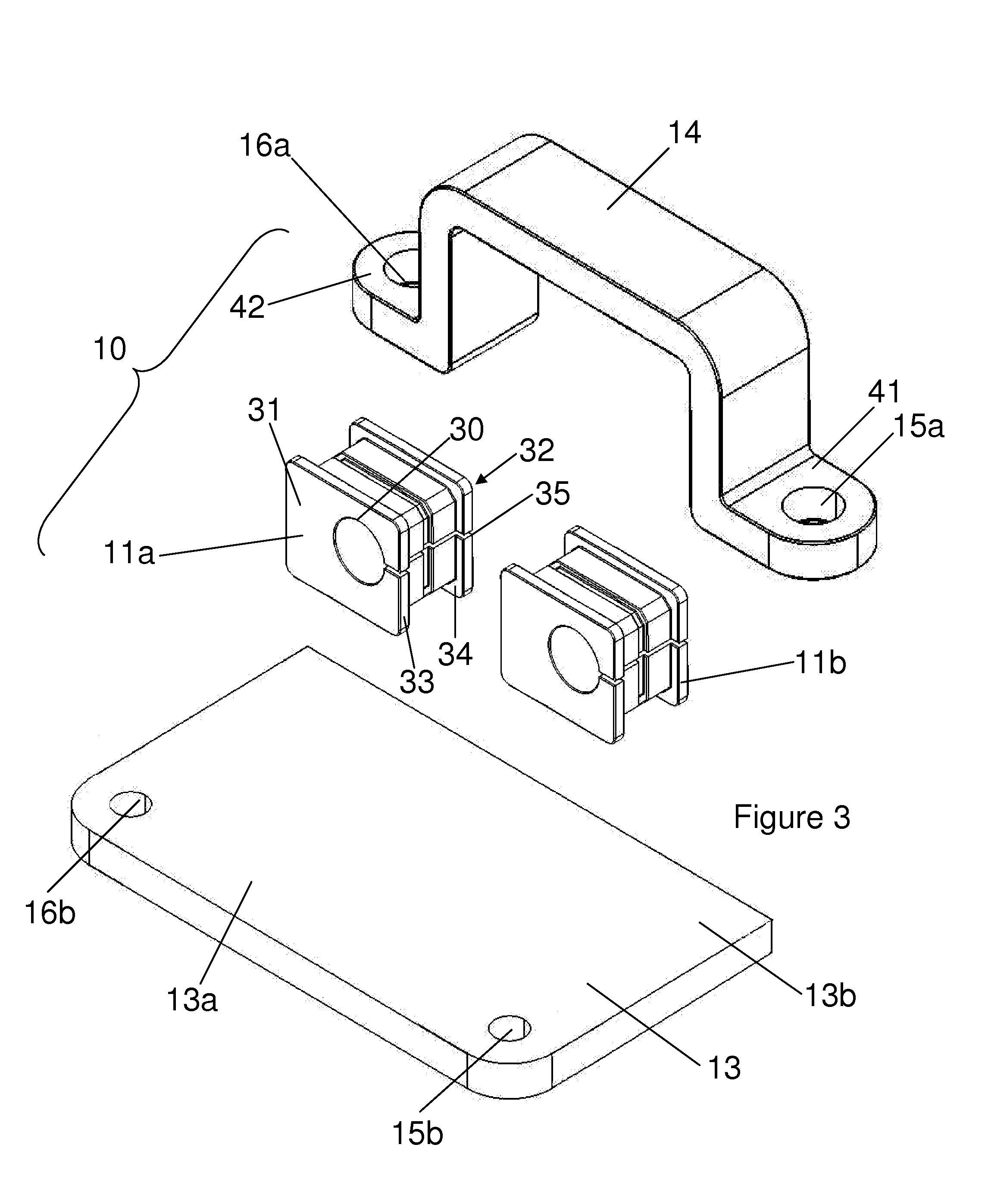
[0039]FIG. 3 illustrates an exploded view of the clamp block assembly 10 so as to show the constituent parts of the clamp block assembly 10 in greater detail. The clamp blocks 11a, 11b. Each clamp block is generally cuboid with a through-hole 30 extending between opposing end faces 31, 32 of the clamp block. The end faces project slightly beyond sides of the clamp block so as to define flanges 33, 34. A slit 35 extends from the through-hole 30 to on...

Example

[0057]In the second embodiment the clamp blocks 111a, 111b have through holes of different diameters but this is optional, as discussed previously.

[0058]It will be appreciated that one or more features of the first and second embodiments may be incorporated in the other.

[0059]Where the clamp block assembly includes more than two clamp blocks, several of the projections depending from the saddle top cover may be provided. If there are many clamp blocks in the clamp block assembly then one or more additional fastener locations may be provided between the first and second parts of the clamp, e.g. between groups of the clamp blocks. In this case the saddle top cover may have an undulating profile.

[0060]The clamp block assembly may be used in both forward and retro-fit markets with only minor adaption. The assembly is designed to be simply removed and replaced using standard tools and fasteners.

[0061]Although the invention has been described above with reference to one or more preferred ...


PUM


Abstract

A clamp block assembly for securing hydraulic pipes, the clamp block assembly comprising one or more unitary clamp blocks of deformable material each having a through hole for receiving a respective pipe, and a clamp adapted to apply a predetermined load around the clamp block(s).

Description

FIELD OF THE INVENTION[0001]The present invention relates to a clamp block assembly for securing hydraulic pipes. In particular, though not exclusively, the clamp block assembly is used to secure hydraulic pipes in an aircraft. The clamp block assembly may alternatively be used to secure other pipe work, such as pneumatic pipes, in a variety of vehicular and non-vehicular applications.BACKGROUND OF THE INVENTION[0002]Aviation regulators, such as JAR (Joint Aviation Regulation), FAR (Federal Aviation Regulation) and EASA (European Aviation Safety Agency), specify requirements for fixed wing aircraft on the performance and reliability of the hydraulic systems that provide power to the aircraft's wing flight controls throughout the service life of the aircraft.[0003]Hydraulic pipes run through various regions of the aircraft, e.g. along the aircraft wing trailing edge close to the rear structural spar. To help meet the performance and reliability requirements of the hydraulic systems, ...

Claims


Application Information

Patent Timeline
IPC IPC(8): F16L3/12
CPCF16L3/1222F16L3/227F16L3/2235F16L55/035F16L3/18
Inventor EDMOND, GEORGEDICKINSON, PHILIPSIANGOLIS, NICHOLAS
Owner AIRBUS OPERATIONS LTD
Why Eureka
Try Eureka