Apparatus and Method for Inductive Power Transfer on an Electrified Roadway Using a Rotating Secondary Inductor

a secondary inductor and inductive power technology, applied in the control of dynamo-electric converters, charging stations, transportation and packaging, etc., can solve the problems of inability to solve the problem of electric vehicle transportation, inability to charge lithium-ion batteries at the same time, and limitations of electric vehicles such as cars and trucks to store or transmit electricity onboard the vehicle. , to achieve the effect of reducing the power requirements of each tire and increasing the magnetic flux

Active Publication Date: 2013-08-22
UNIVERSITY OF VERMONT
View PDF6 Cites 13 Cited by
  • Summary
  • Abstract
  • Description
  • Claims
  • Application Information

AI Technical Summary

Benefits of technology

This patented technology relates to improving the performance of induction systems like those commonly employed in electric motor/generator applications. It involves utilizing specialized metallic components called iron cores wrapped about certain parts of a tread made from rubber instead of traditional steel plated cables. These iron core elements act as both primary and secondaries receptacles for electric current flowing through them when they come into contact with rails along their length. By adding these iron cores alongside regular steel ones at specific locations throughout the tread design, we aim to reduce power demands while maintaining good efficiency.

Problems solved by technology

The technical problem addressed in this patent text is the limitation of current solutions for electric vehicle transportation, such as batteries and fast charging, battery swapping, and plug-in hybrid vehicles. These solutions have limitations in terms of storage and transmission of electricity onboard the vehicle, which affects their range and efficiency. The patent proposes a new solution to overcome these limitations by using an inductive pick-up system to transmit power to electric vehicles. However, the problem of an inductive pick-up hanging under the car close to the road in snow and ice is a previously unsolved problem, which makes it unsuitable for less-than-ideal road conditions.

Method used


Image

  • Apparatus and Method for Inductive Power Transfer on an Electrified Roadway Using a Rotating Secondary Inductor
  • Apparatus and Method for Inductive Power Transfer on an Electrified Roadway Using a Rotating Secondary Inductor
  • Apparatus and Method for Inductive Power Transfer on an Electrified Roadway Using a Rotating Secondary Inductor

Examples


Embodiment Construction

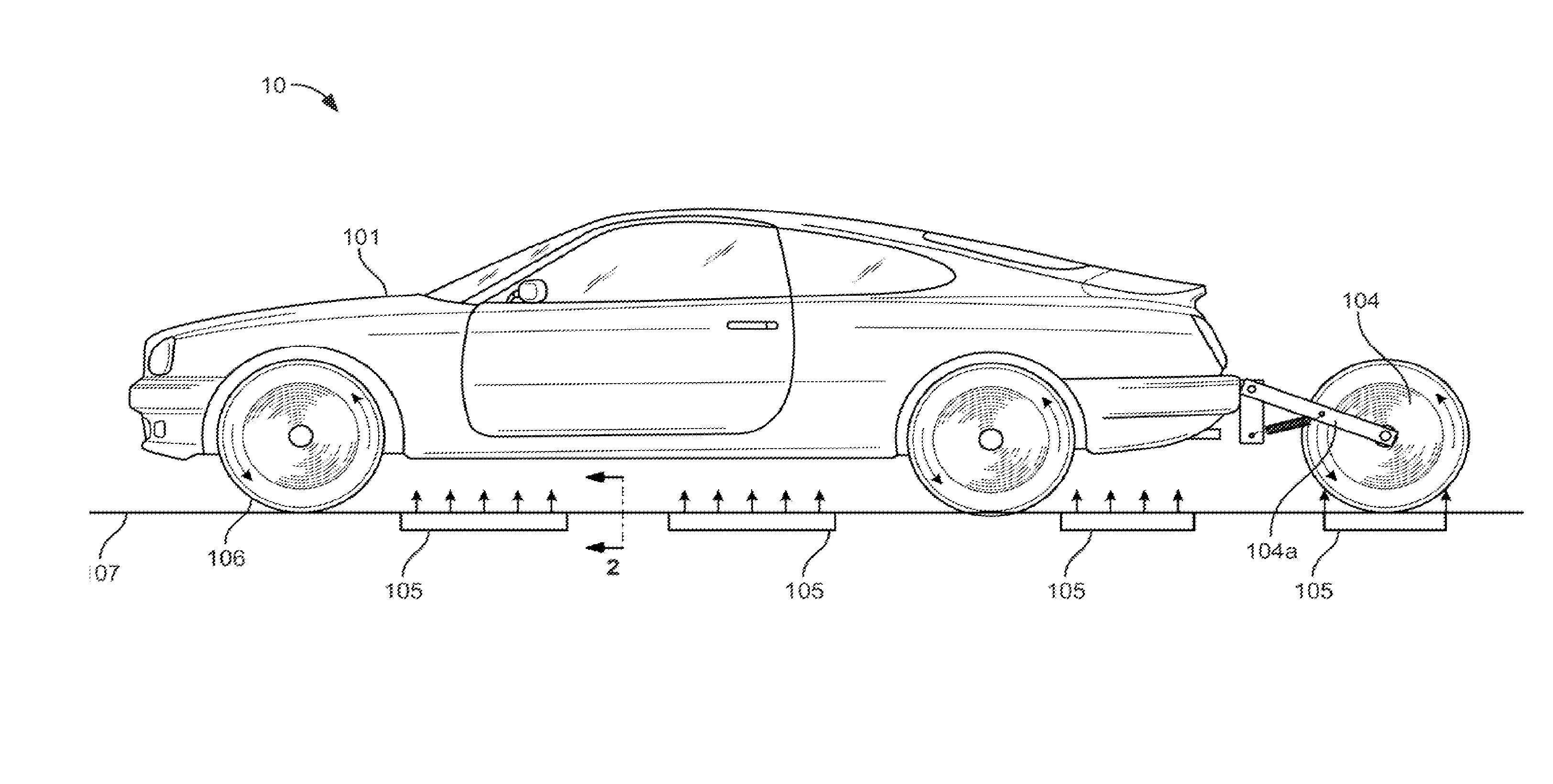
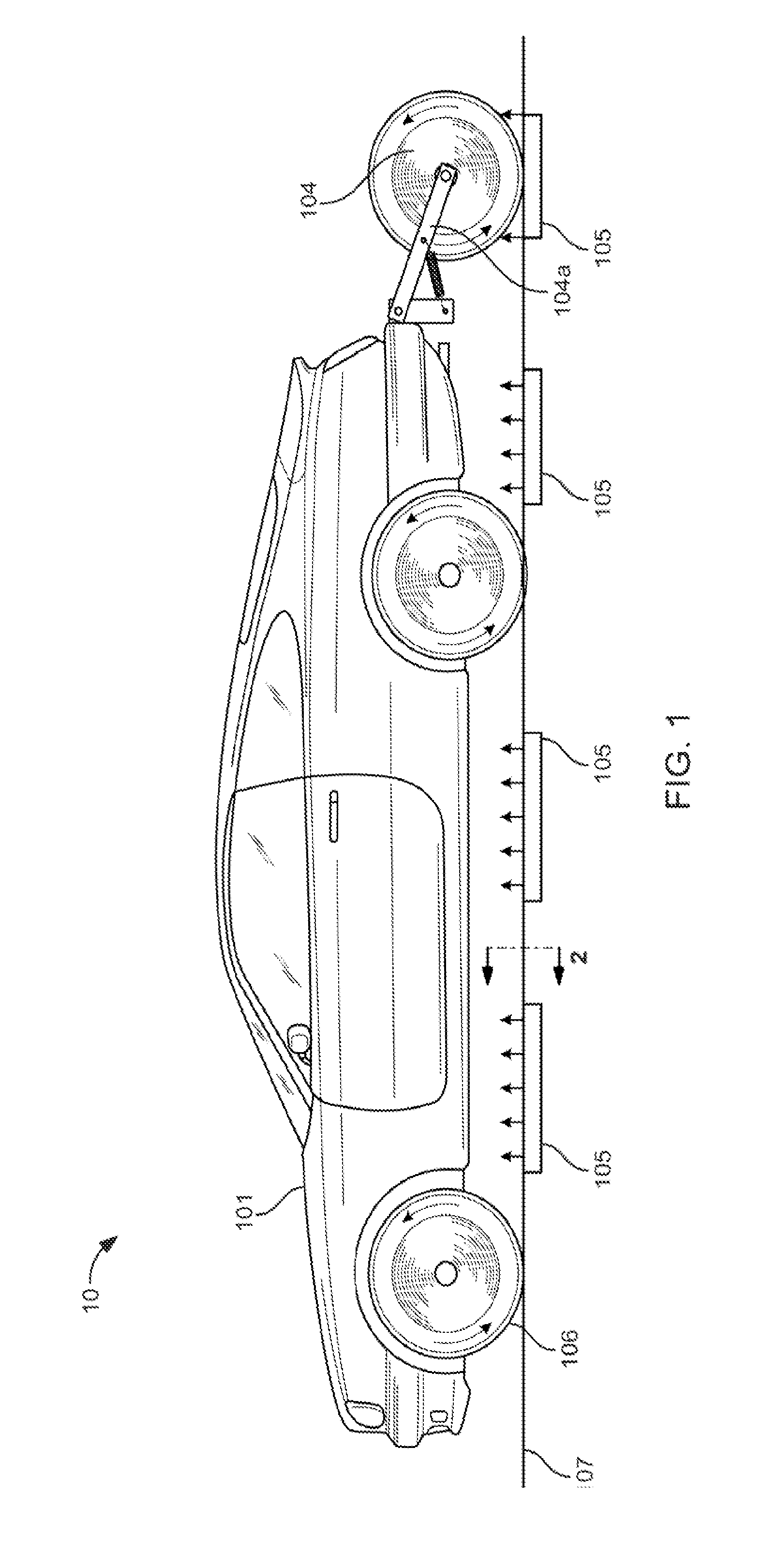
[0036]Referring now to FIG. 1, there is shown a schematic diagram illustrating one embodiment of the present invention of an inductive power transfer apparatus embedded within electric vehicle tires 106 on an electrified roadway 107, The energy transmission arrays 105 are preferably disposed beneath a roadway surface, although transmission systems disposed on the surface are contemplated as well. The embedded energy reception system 106 is on one or more axels of vehicle 101, which uses the transferred electrical power to either charge an onboard energy storage device unit (FIG. 3, item 18) or for propulsion / use directly. It will also be that any suitable number of embedded energy reception system 106 configurations may be employed, such as a “fifth” wheel 104 mechanically linked to vehicle 101 via mechanical linkage 104A shown in FIG. 1

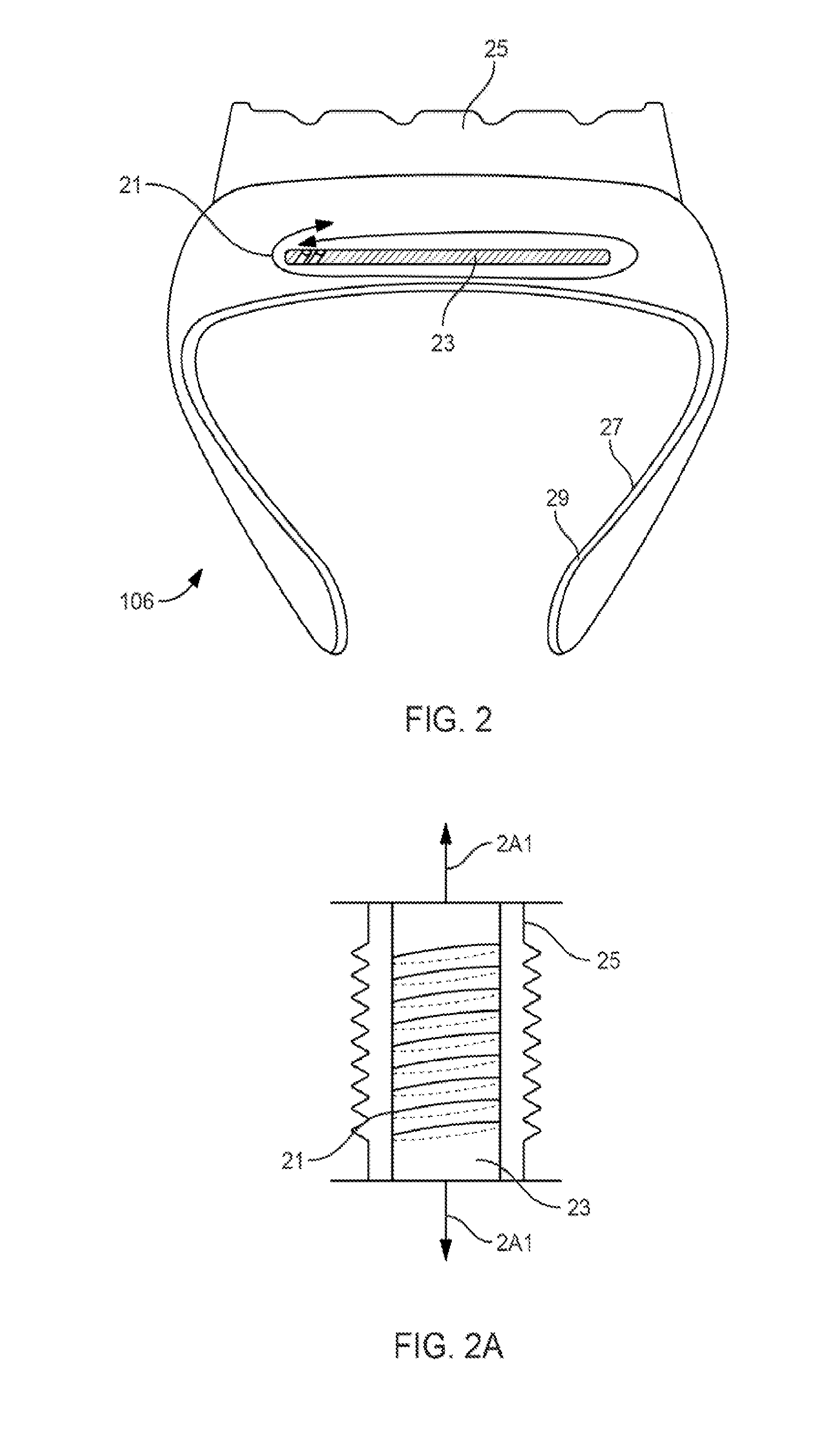
[0037]Referring also to FIG. 2, there is shown is a cross section schematic diagram of electric vehicle tires 106 illustrating implementation of an ...


PUM


Abstract

The invention described herein provides an energy transfer system via a tire based inductor system. By using the tire, the area inside the tire, the tire rim, or the wheel as the inductive pick-up for a powered roadway system the prior art problems are solved. Namely, since the tire/wheel is always in contact, or near contact with the road, the air gap is reduced to a minimum, and substantially fixed, distance. By mounting the secondary on the perimeter of a wheel, relative motion between the road and inductor is minimized In addition, the pick-up can be encased in the tire, eliminating the problem of road debris, snow and ice entirely. Also, some heating of the tire due to electrical losses may enhance traction and tread performance on snowy or wet roads. In all configurations, the vehicle's wheel suspension adjusts vertically adjusting for road imperfections and obstacles.

Description


Claims


Application Information

Patent Timeline
Owner UNIVERSITY OF VERMONT
Why Eureka
Try Eureka