
Electronic component

a technology of electronic components and components, applied in the direction of waveguides, basic electric elements, waveguide devices, etc., can solve the problems of complicated design of laminated type dielectric filters b>500/b>, and achieve the effect of easy design of electronic components

Active Publication Date: 2013-08-22
MURATA MFG CO LTD
View PDF6 Cites 3 Cited by
  • Summary
  • Abstract
  • Description
  • Claims
  • Application Information

AI Technical Summary

Benefits of technology

The patent text is describing a technology that makes it easy to create electronic components. This can be useful for engineers who are trying to design new electronic devices or improve existing ones.

Problems solved by technology

Therefore, the design of the laminated type dielectric filter 500 may become complicated.

Method used


Image

  • Electronic component
  • Electronic component
  • Electronic component

Examples


Embodiment Construction

[0020]Hereinafter, an electronic component according to preferred embodiments of the present invention will be described.

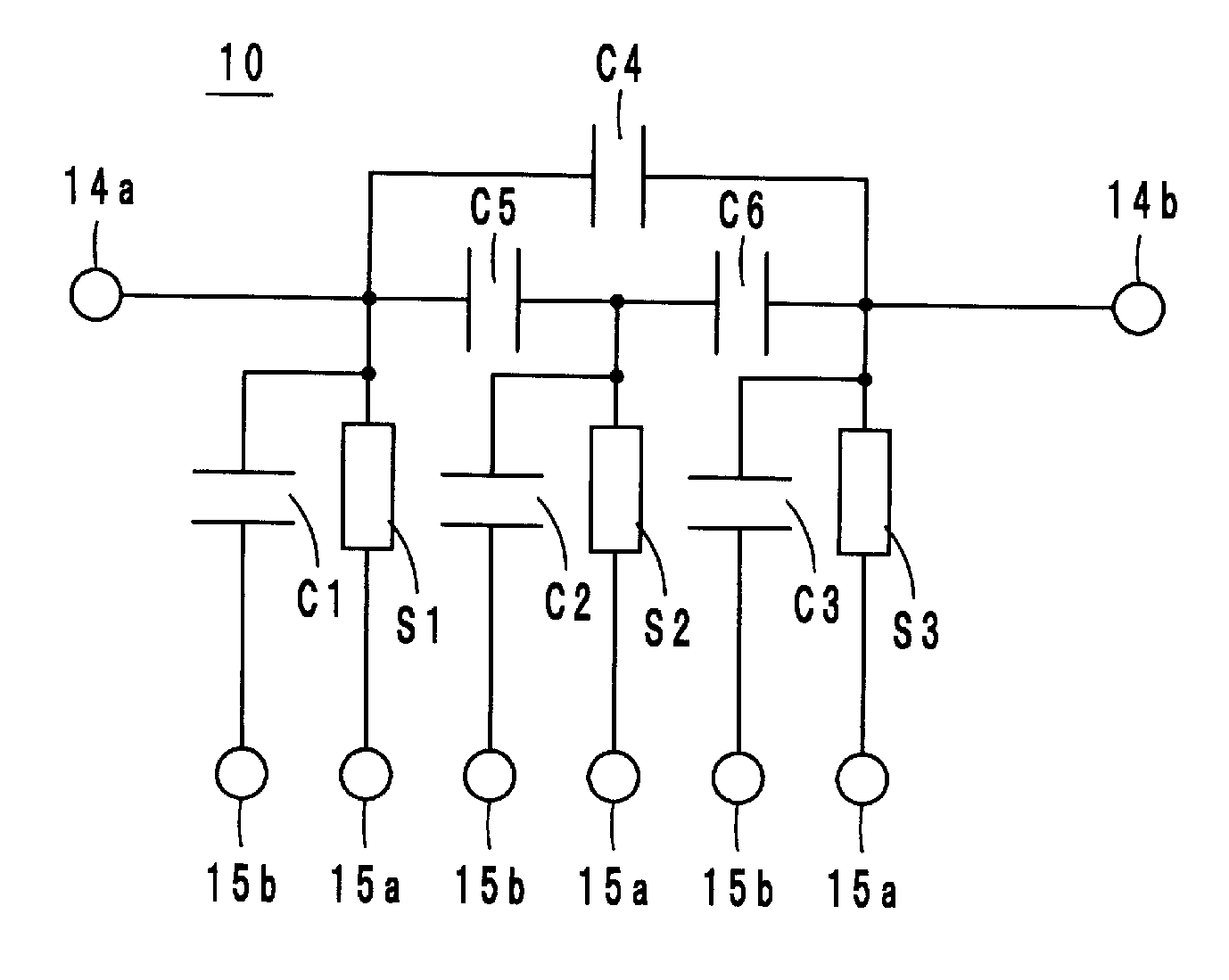
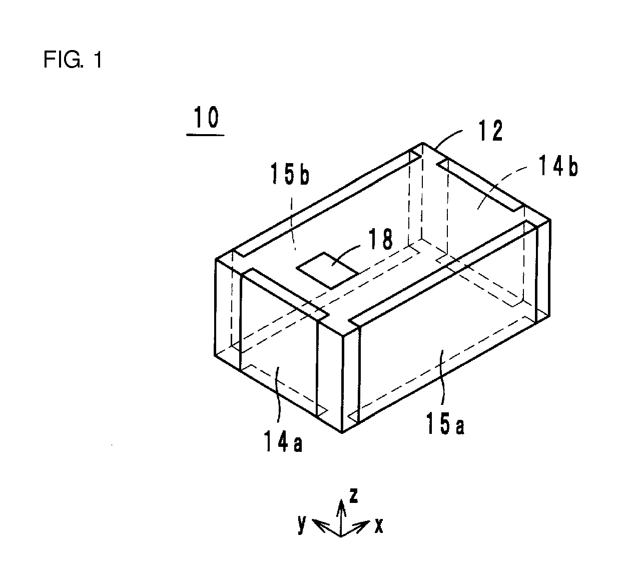
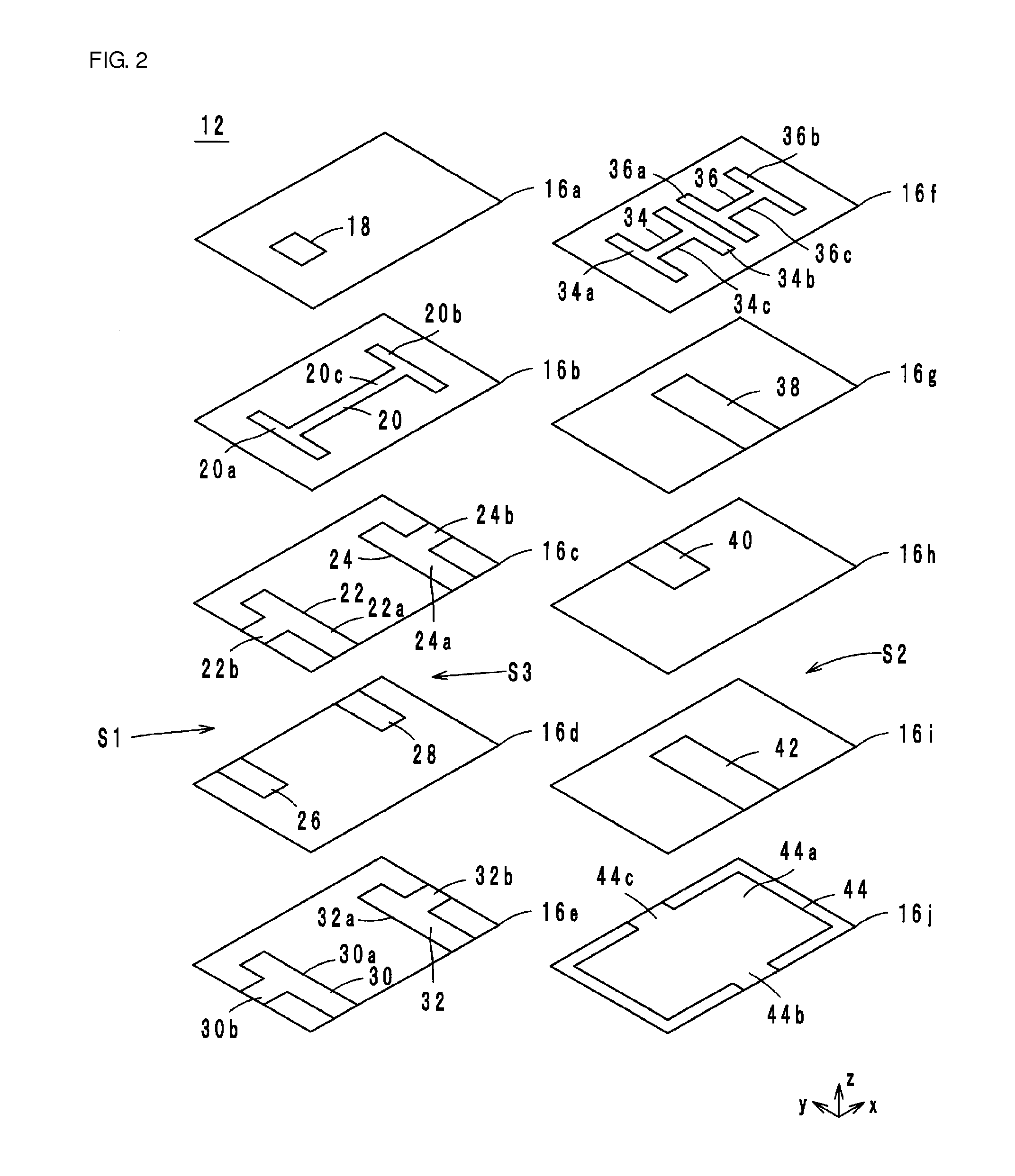
[0021]Hereinafter, the structure of an electronic component according to a preferred embodiment of the present invention will be described with reference to drawings. FIG. 1 is the appearance perspective view of an electronic component 10 according to the present preferred embodiment. FIG. 2 is the exploded perspective view of the electronic component 10 according to the present preferred embodiment. FIG. 3 is the cross-section structure diagram of the electronic component 10 according to the present preferred embodiment. FIG. 4 is the equivalent circuit diagram of the electronic component 10 according to the present preferred embodiment.

[0022]The electronic component 10 preferably is used as, for example, a band pass filter, and as illustrated in FIG. 1 to FIG. 3. The electronic component 10 preferably includes a laminated body 12, external electrodes 14 (14a, 14...


PUM


Abstract

An electronic component includes a laminated body including a plurality of insulator layers laminated on each other in a lamination direction. A first strip line resonator is provided within a first region in the laminated body. A second strip line resonator is provided within a second region in the laminated body. A third strip line resonator is provided within the first region in the laminated body, and in a planar view in a lamination direction, the third strip line resonator and the first strip line resonator sandwich therebetween the second strip line resonator. A coupling conductor capacitively couples the first strip line resonator and the third strip line resonator.

Description

BACKGROUND OF THE INVENTION[0001]1. Field of the Invention[0002]The present invention relates to an electronic component, and relates to an electronic component including a resonator.[0003]2. Description of the Related Art[0004]As an electronic component of the related art, for example, a laminated type dielectric filter described in Japanese Unexamined Patent Application Publication No. 2006-67222 has been known. FIG. 9 is the appearance perspective view of a laminated type dielectric filter 500 described in Japanese Unexamined Patent Application Publication No. 2006-67222. In FIG. 9, the lamination direction of the laminated type dielectric filter 500 is defined as a z-axis direction. In a planar view of the laminated type dielectric filter 500 in the z-axis direction, a direction in which a long side extends is defined as an x-axis direction, and a direction in which a short side extends is defined as a y-axis direction.[0005]The laminated type dielectric filter 500 is used as, f...

Claims


Application Information

Patent Timeline
IPC IPC(8): H01P1/203
CPCH01P1/20309H01P1/20345
Inventor MASUDA, HIROSHI
Owner MURATA MFG CO LTD
Learn More