
Method and device for coded modulation

a coded modulation and channel technology, applied in the field of digital communication systems, can solve the problems of inability to directly use root ldpc codes, inability to study error performance on bf channels, and inability to use traditional tools for coding gain optimization, such as standard exit charts, to achieve the effect of reducing the number of bf channel capacity-achieving codes

Inactive Publication Date: 2013-08-22
UNIV GENT
View PDF0 Cites 25 Cited by
  • Summary
  • Abstract
  • Description
  • Claims
  • Application Information

AI Technical Summary

Benefits of technology

The present invention provides a method for optimizing a coded modulation scheme for communication over a slow fading channel. The method takes into account the randomness of the fading gains and the degree distribution of a parity check matrix in the fading space of the channel. The method selects a coded modulation scheme with a coding rate and a modulation rate that meet the given spectral efficiency. The method also includes steps of mapping the coded bits to a constellation, labelling the constellation, and optimizing the degree distribution of the parity check matrix in the fading space. The invention solves the problem of prior art solutions where the outage probability is not optimal. The method can be implemented in a transmitter device and aims to improve the performance of the coded modulation scheme in a slow fading channel.

Problems solved by technology

However, few capacity-achieving codes are known for the BF channel.
However, these root LDPC codes are different from standard random LDPC codes and therefore, the traditional tools for coding gain optimization, such as standard EXIT charts, cannot be directly used for root LDPC codes.
Also, it was stated in the Ph.D. thesis of A. Guillén i Fàbregas (“Concatenated codes for block-fading channels”, EPFL, June 2004), that EXIT charts are not a suitable tool for studying error performance on BF channels.
Next, the authors introduced a new family of LDPC codes, achieving full-diversity, but the degree distributions of this family were never optimized either.
The performance is poor, because the solution is not adapted to the context.
However, they have not been extended and simulated for other coding rates than Rc=0.5.
Furthermore, linear-time encoding with root LDPC codes is not trivial and standard optimization techniques, such as EXIT charts, have not been modified yet for root LDPC codes.
Finally, off the shelf standard random LDPC codes cannot be used, which increases the implementation cost of root LDPC codes for chip designers.

Method used


Image

  • Method and device for coded modulation
  • Method and device for coded modulation
  • Method and device for coded modulation

Examples


Embodiment Construction

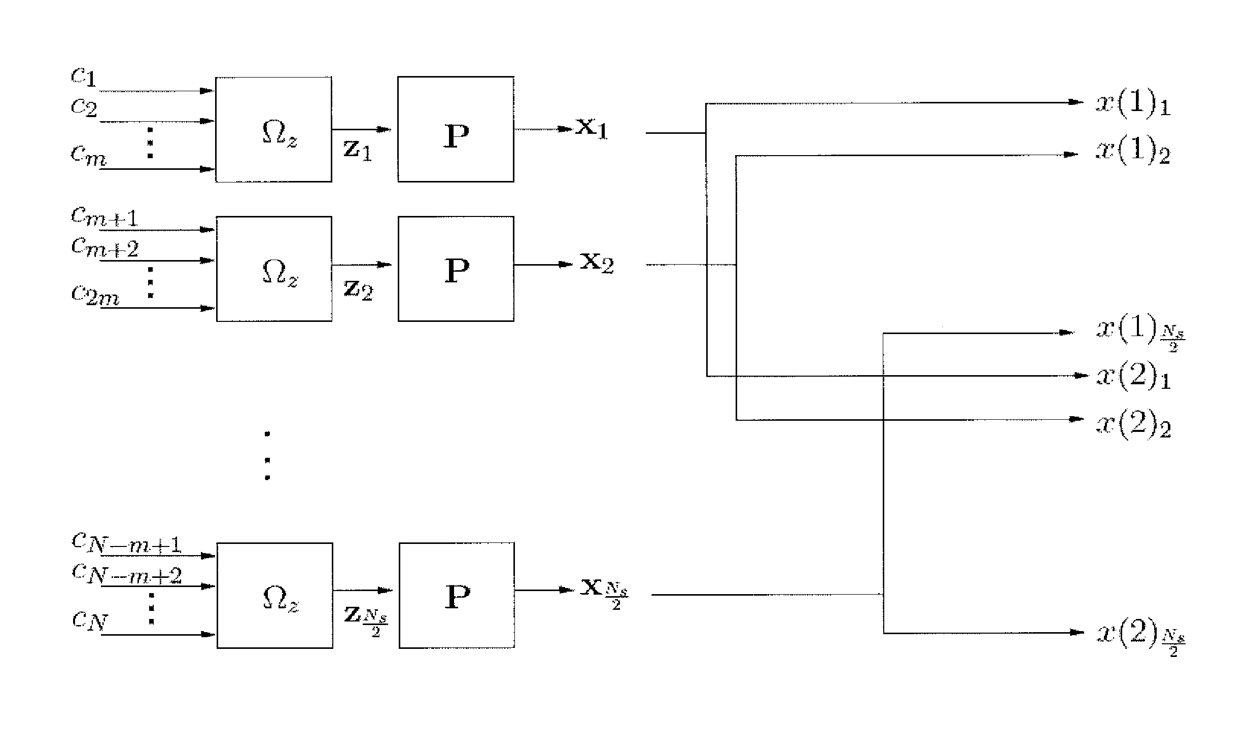
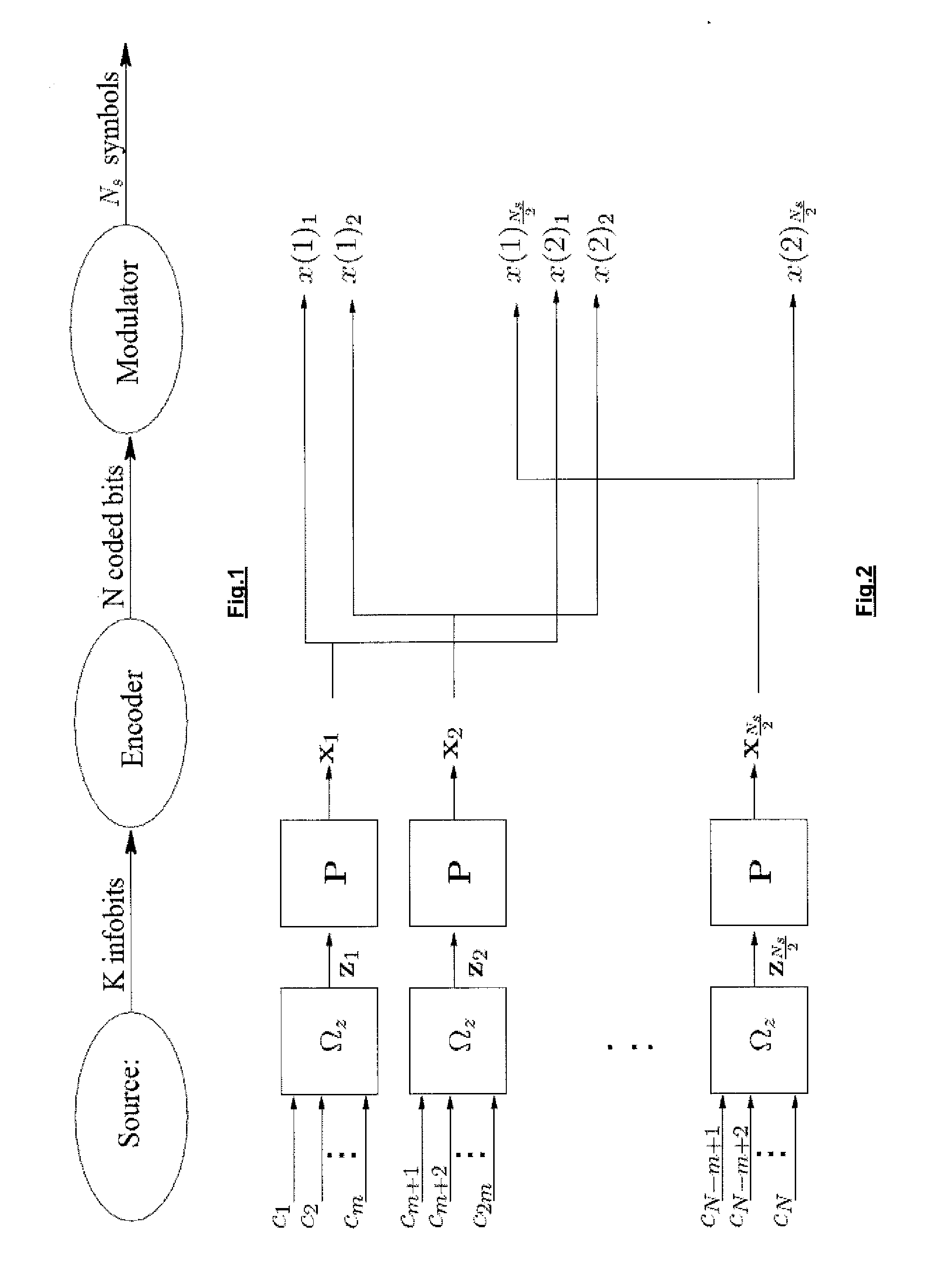
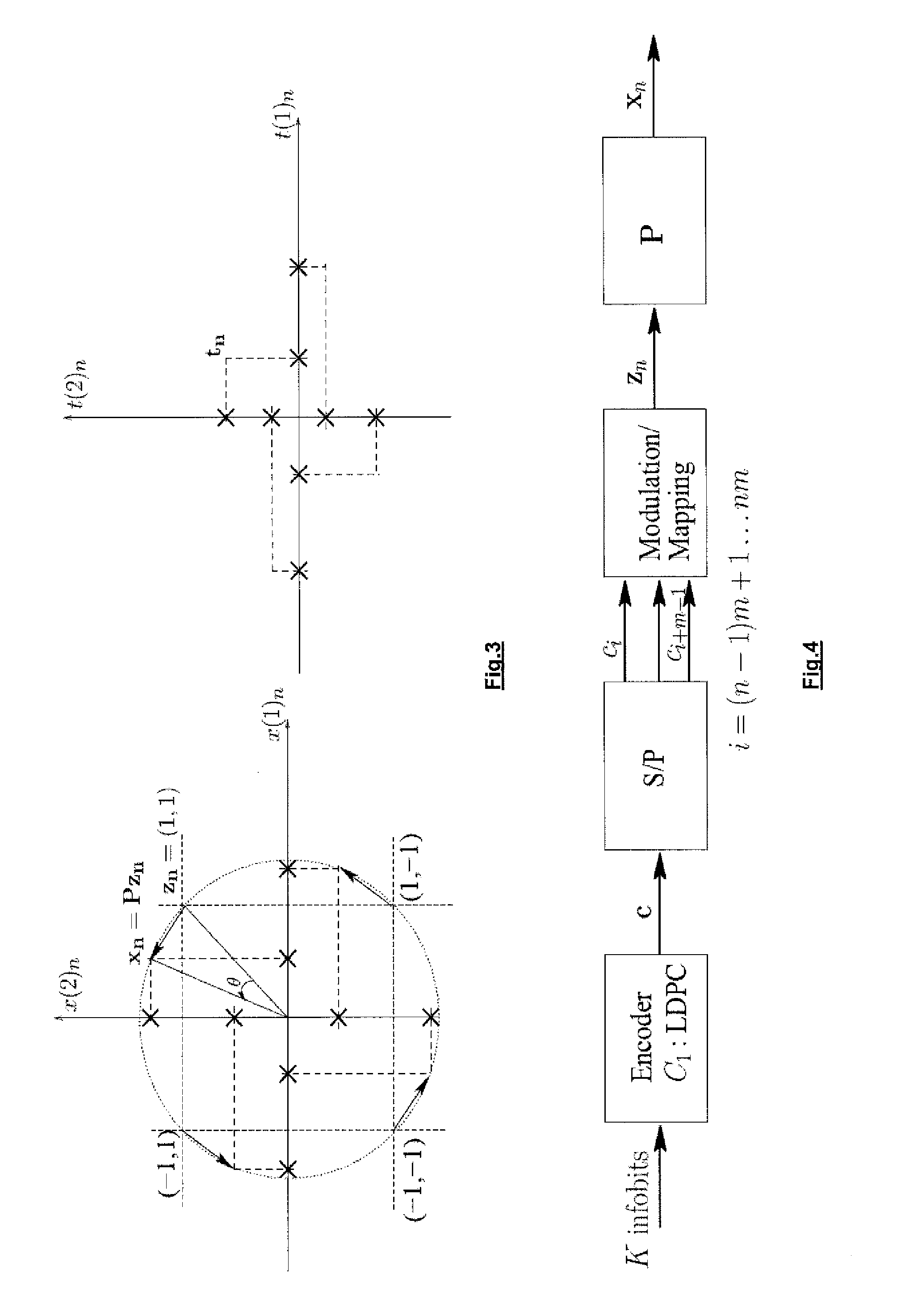
[0065]In one aspect the invention describes a method for obtaining a coded modulation scheme with optimized performance for block fading channels in the sense that it minimizes the transmitted energy per information bit for a certain quality of transmission and a certain spectral efficiency. The solution can be close to optimal, preferably as close as possible, in the sense that it approaches the achievable lower bound (i.e., the outage probability), as determined in the above-mentioned paper by Duyck et al. In the fading space this means that the code boundary must approach the outage boundary as close as possible. This requires designing a good mapping scheme and error-correcting code.

When implementing a practical system approaching this lower bound, one of the challenges is to describe how the labelling from coded bits to modulation points in a multi-dimensional constellation occurs (M! different labellings exist for an M-point constellation, whereby the notation M! denotes the f...


PUM


Abstract

A method for optimising a coded modulation scheme with a given spectral efficiency for communication over a fading channel represented / identified by B fading gains, wherein B is an integer number expressing the ratio between a code word duration and the duration over which the fading remains constant. The fading gains belong to a B-dimensional space of fading gains.

Description

FIELD OF THE INVENTION[0001]The present invention generally relates to the field of digital communication systems. More in particular, it deals with coded modulation techniques for slow fading communication channels.BACKGROUND OF THE INVENTION[0002]In a digital communication system the transmitter takes information bits to be communicated and converts them into a form suitable for transmission to the receiver. This is performed by encoding (protecting) information bits at the transmitter with an error correcting code and subsequently mapping the coded bits to a sequence of symbols. The symbols are then transmitted over a communication channel to a receiver. The receiver captures the channel output and tries to recover the information bits. Hence, a practical transmission scheme is described by an error-correcting code and means for performing a mapping function.[0003]The channel considered in the context of the present invention includes fading experienced between the transmitter an...

Claims


Application Information

Patent Timeline
Patent Type & Authority Applications(United States)
IPC IPC(8): H04L27/00
CPCH03M13/1102H03M13/255H03M13/258H03M13/2957H04L27/0012H04L1/0009H04L1/0041H04L1/0058H04L27/2601H03M13/6325
Inventor BOUTROS, JOSEPHMOENECLAEY, MARCDUYCK, DIETER
Owner UNIV GENT
Learn More