Connector

a technology of connecting parts and connectors, applied in the direction of coupling device connection, securing/insulating coupling contact members, electrical apparatus, etc., can solve the problems of increasing assembly man-hours, increasing the number of contact terminals provided in the connector, and increasing the number of parts, so as to facilitate the manufacture of the housing, enhance the strength of the holding part holding the contacts, and the length of the leading end

Active Publication Date: 2013-08-22
JST MFG CO LTD
View PDF8 Cites 3 Cited by
  • Summary
  • Abstract
  • Description
  • Claims
  • Application Information

AI Technical Summary

Benefits of technology

[0027]With the connector according to the fifth and the sixth aspect, strength of the holding part holding the contacts can be enhanced and the manufacture of the housing is facilitated.
[0028]With the connector according to the seventh to the tenth aspect, the length of the leading end of each of the contact protruding from the holding part can be further reduced, so that the alignment accuracy can be more improved. In this case, the length of the holding part is adjusted to correspond to a through hole formed in the substrate. As a result, the contact can be more rigidly held and the alignment accuracy of the leading end can be improved.
[0029]With the connector according to the eleventh and the twelfth aspect, even with a so-called top-type connector attached to the substrate at a right angle, the same effects as those in the first and the second aspects can be obtained.
[0030]With the connector according to the thirteenth aspect, since the contacts are formed of wire rods, they are resistant to stress applied in the drawing direction and can preve

Problems solved by technology

However, because of ever-increasing multifunctionality and high performance of electronic devices in recent years, the devices themselves have been made smaller and become space-saving, and the number of contact terminals provided in the connector has increased.
However, there is a problem that the number of parts increases when the compensation plate is used in the connector.
In addition, increase in the number of parts leads to an increase in assembly man-hours, and the footprint of parts on the substrate becomes large, so that downsizing and space-saving of the connector may not be achiev

Method used


Image

  • Connector
  • Connector
  • Connector

Examples


embodiment 1

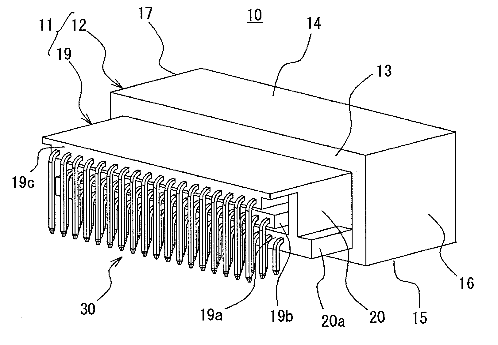
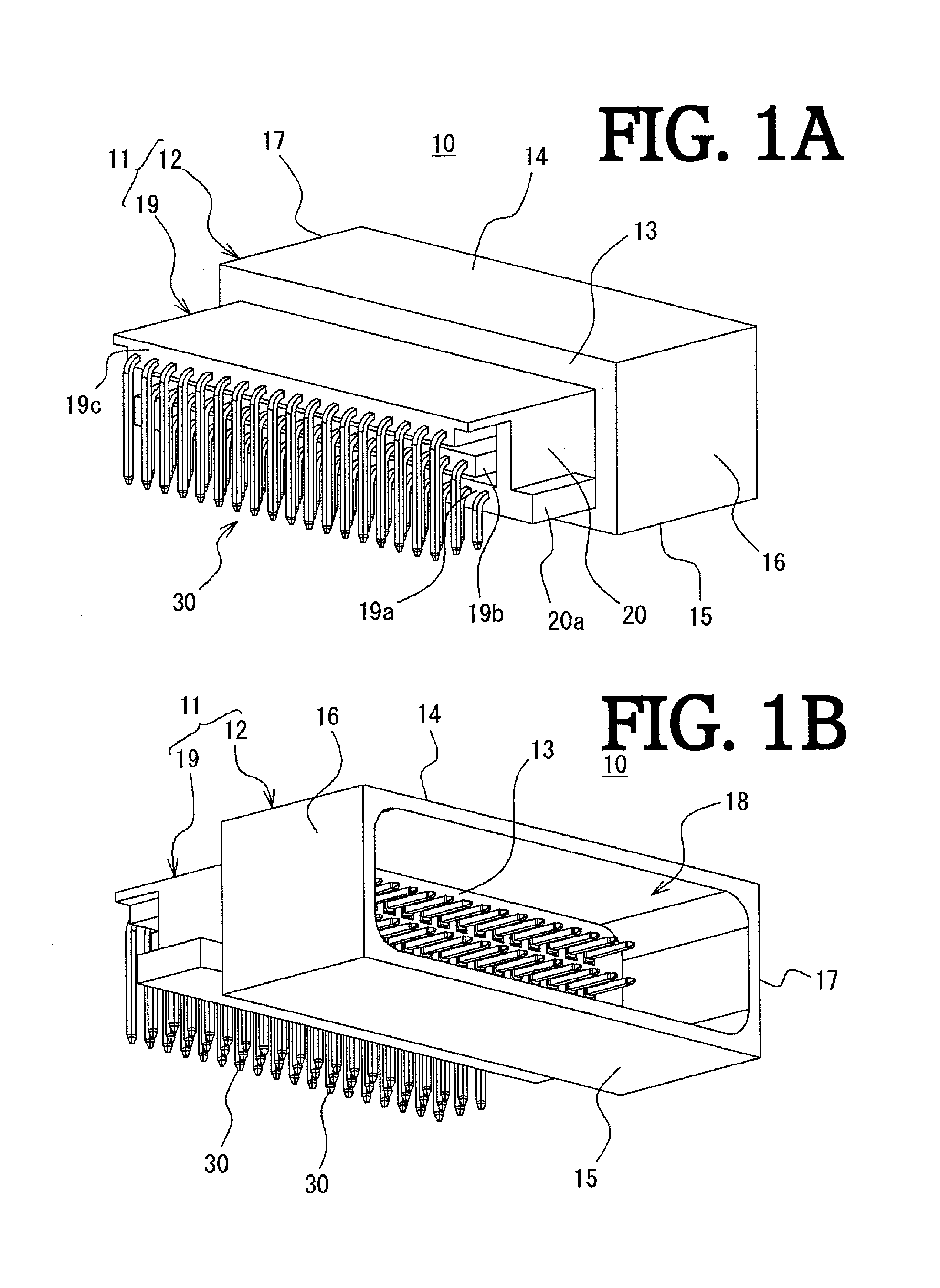
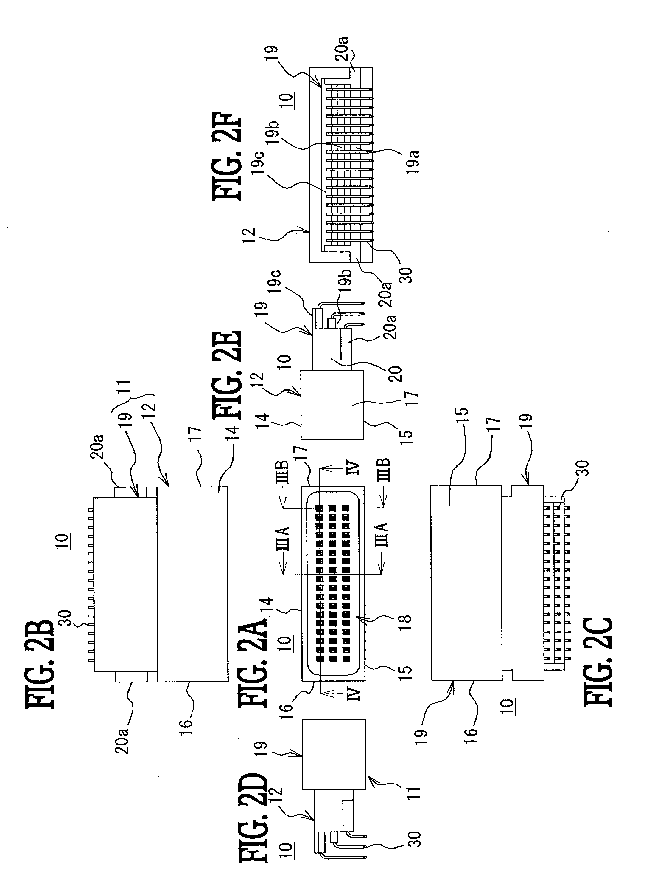
[0048]With reference to FIGS. 1 to 8, a connector according to Embodiment 1 will be described. As illustrated in FIGS. 1 and 2, a connector 10 of Embodiment 1 includes a housing 11 formed of insulating material and a plurality of contacts 30 mounted on the housing 11. The connector 10 of Embodiment 1 is a so-called side-type connector 10 (refer to FIG. 8) in which the contacts 30 mounted on the housing 11 are parallel to a substrate 36, so that leading ends of the contacts 30 to be described later are bent at a substantially right angle to be orthogonal to the substrate 36. The connector 10 of Embodiment 1 is described using a connector in which three arrays of the contacts 30 are arranged. Hereinbelow, each of the components will be described.

[0049]The housing 11 of Embodiment 1 includes a mounting part 12 mounted to a counterpart connector (not shown) and a holding part 19 extended from the mounting part 12 by a predetermined length and holding the contacts 30, and is integrally f...

embodiment 2

[0072]A connector according to Embodiment 2 will be described with reference to FIGS. 9 to 13. The connector described in Embodiment 1 is a so-called side-type connector, on the other hand, the connector according to Embodiment 2 is a so-called top-type connector that is vertically mounted on a substrate. In the connector according to Embodiment 2, only part of the shape of the housing and the contact is different from that of the connector according to Embodiment 1, and other components are the same. Therefore, the same components as those of the connector of Embodiment 1 will be denoted by the same reference numerals, and detailed description thereof will not be repeated here.

[0073]As illustrated in FIGS. 9 and 10, a connector 10A according to Embodiment 2 includes a housing 11A formed of insulating material and a plurality of contacts 30A mounted on the housing 11A. With respect to the connector 10A of Embodiment 2, a case where the contacts 30A are aligned in one array will be d...


PUM


Abstract

A connector includes a housing and contacts. Each of the contacts includes a leading end, a connecting part, a held part, and a flange part. The housing has a holding part having a contact insertion hole into which the held part is inserted. The contact insertion hole includes: a first insertion hole in which a side surface of the held part of the contact is held; a second insertion hole formed in a size that holds one opposite side surface of the held part of the contact, and having a space on the other opposite side surface side, the second insertion hole being formed to be longer than the first insertion hole; and a flange holding part. The held part of the contact is made longer than the leading end of the contact. This configuration can improve alignment accuracy of the contacts without using a compensation plate.

Description

TECHNICAL FIELD[0001]The present invention relates to a connector having a plurality of contacts mounted on a substrate. Specifically, the present invention relates to a connector that can improve alignment accuracy of the contacts without using other components such as a compensation plate for aligning the contacts when the connector is mounted on the substrate.BACKGROUND ART[0002]A connector has been used for connecting an electronic control system installed in a vehicle such as an automobile with other electronic devices. However, because of ever-increasing multifunctionality and high performance of electronic devices in recent years, the devices themselves have been made smaller and become space-saving, and the number of contact terminals provided in the connector has increased. Conversely, the footprint of connectors mounted on the substrate has been reduced and the contact terminals have become more closely arranged.[0003]Such a connector generally includes a housing, a contac...

Claims


Application Information

Patent Timeline
IPC IPC(8): H01R13/516
CPCH01R12/724H01R13/516H01R13/41H01R12/727
Inventor SHIRAISHI, MAKOTOHAYASHI, KENTARO
Owner JST MFG CO LTD
Why Eureka
Try Eureka