Telescoping Door Mount Exercise Bar

a telescopic, door mount technology, applied in the direction of gymnastic exercise, sport apparatus, muscle exercise devices, etc., can solve the problems of high manufacturing cost, complex mechanical structure of the bar, and inability to support a substantial amount of weight, so as to relieve the pressure on the frictional compressible outer pads

Inactive Publication Date: 2013-08-22
ANAYA RICHARD
View PDF14 Cites 27 Cited by
  • Summary
  • Abstract
  • Description
  • Claims
  • Application Information

AI Technical Summary

Benefits of technology

[0014]The user then performs one or more exercises using the handles or other exercise accessory inserted into the mounting sleeves. The extensible outrigger tubes extending from either end of the horizontal stabilizer tube and abutting the edge of the door stop molding serve to limit the rotational movement of the entire exercise bar so that the user can exercise in security and safety. To move the exercise bar up or down in the door frame:...

Problems solved by technology

However, one obstacle for such devices is that the exercise bar must be able to support a substantial load, at least the user's full body weight, while also providing for easy adjustment of the bar when a new position is desired, or a new length is required to fit door-frames of varying widths.
However, such devices may fail under substantial loads.
This device suffers from at least three weaknesses,...

Method used


Image

  • Telescoping Door Mount Exercise Bar
  • Telescoping Door Mount Exercise Bar
  • Telescoping Door Mount Exercise Bar

Examples


Embodiment Construction

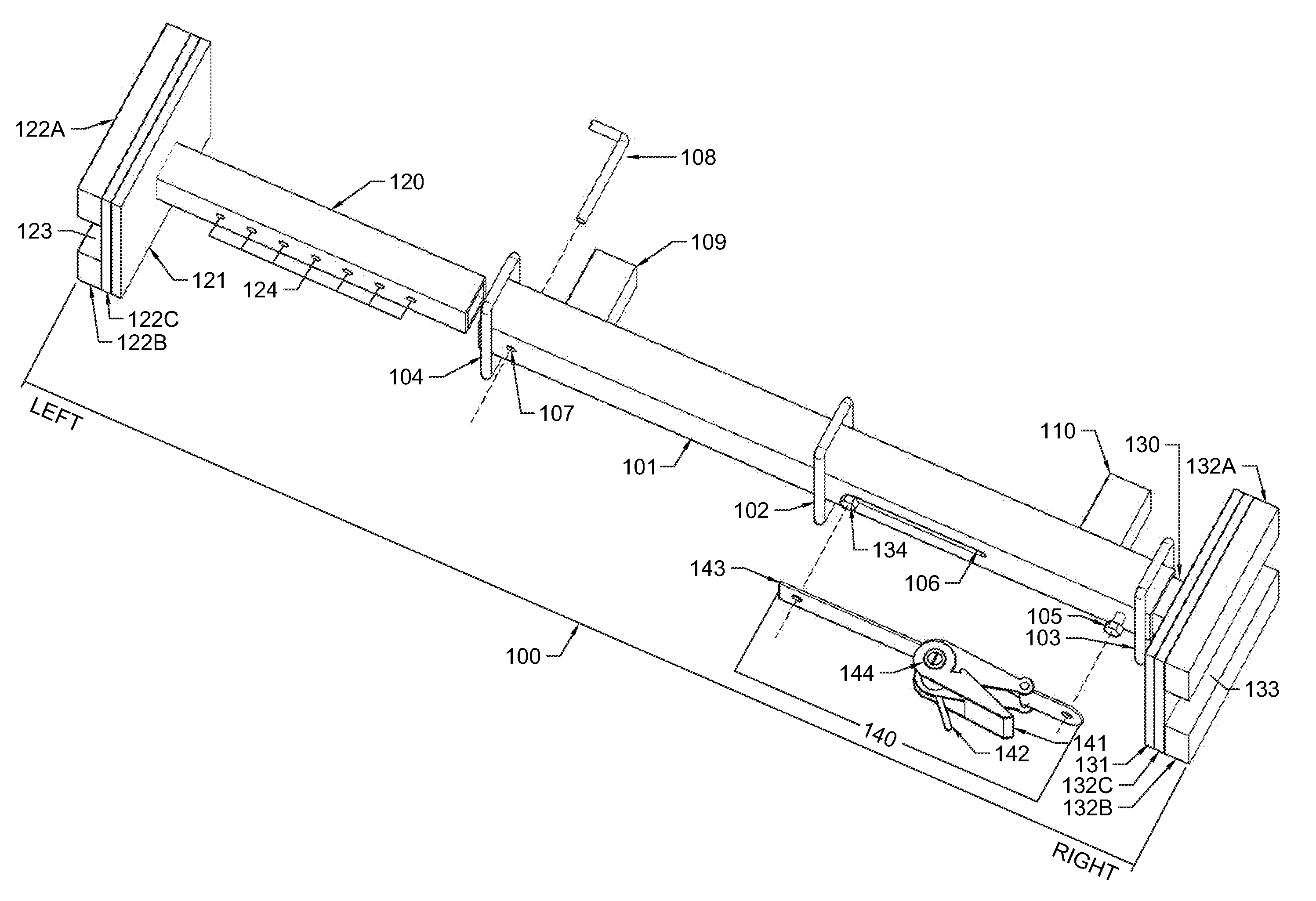
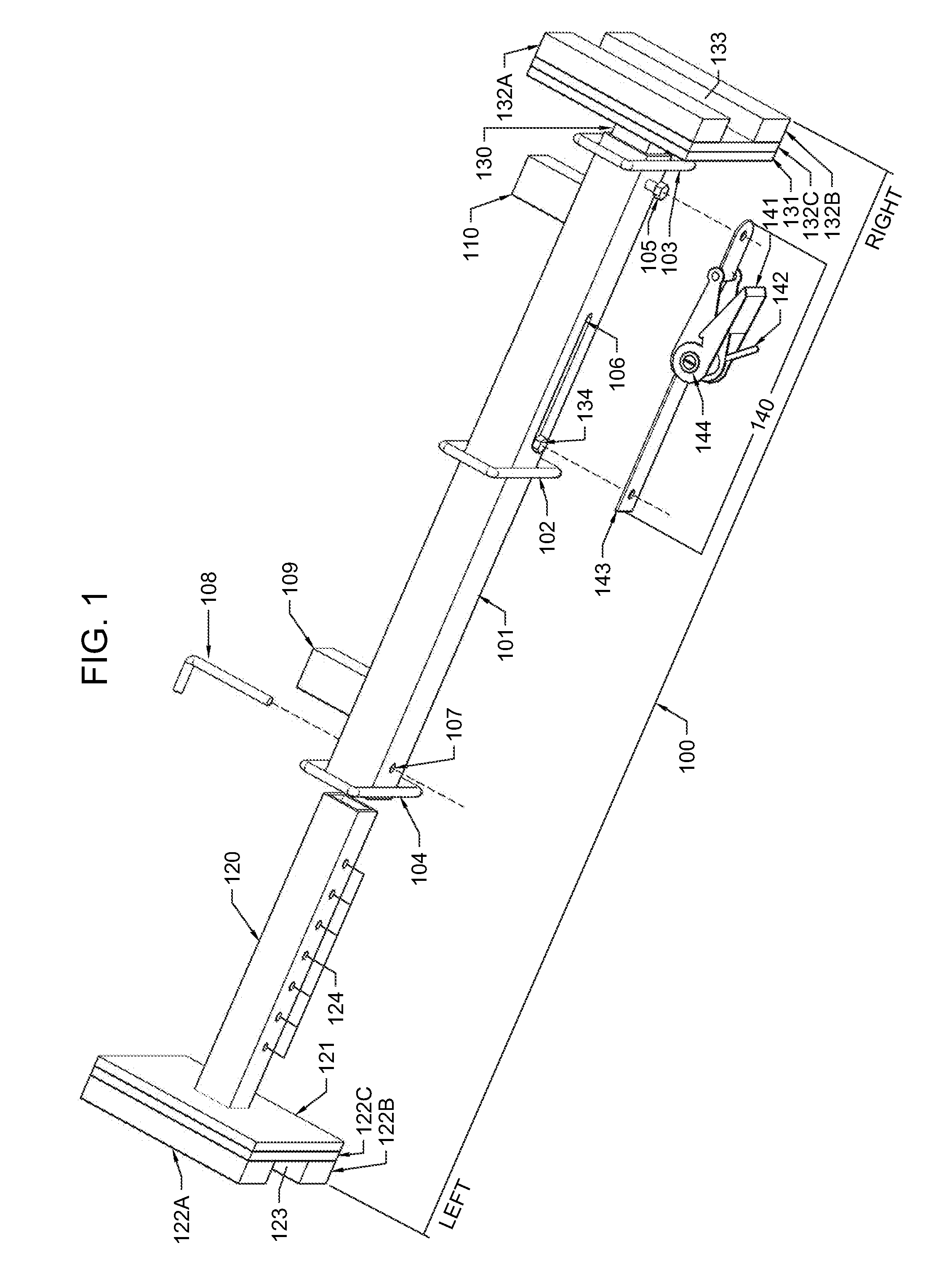
[0019]Referring now to FIG. 1 and FIG. 3, the exercise bar 100 is comprised of central outermost telescoping bar 101, left innermost telescoping bar 120, and right innermost telescoping bar 130. Left innermost telescoping bar 120 and right innermost telescoping bar 130 slide into, and out of, central outermost telescoping bar 101 thereby enabling the user to shorten or lengthen exercise bar 100 to fit within door-frame 300.

[0020]Referring now to FIG. 1, welded or otherwise attached to central outermost telescoping bar 101 at its midpoint and at either end are rectangular rings or other elastic band attachment points 102, 103, and 104. Each of rectangular rings or other elastic band attachment points 102, 103, and 104 is attached to central outermost telescoping bar 101 such that a gap is formed between the front and rear surfaces of central outermost telescoping bar 101 and rectangular rings or other elastic band attachment points 102, 103, and 104. These gaps provide for the attach...


PUM


Abstract

A door-frame mounted exercise bar having two ends, each covered by a frictional, compressible substance, wherein said exercise bar is lengthwise adjustable by means of a ratchet operated strap, thus allowing the user to securely fit the exercise bar into a door-frame. The exercise bar has attachment points for elastic straps and other devices and mounting posts on its top surface. A stabilizer/attachment bar is provided having mounting sleeves aligned to coincide with, and attach to, the mounting posts on top of the exercise bar. These mounting sleeves also serve as attachment points for handles, exercise bars, and other accessories. The stabilizer/attachment bar is lengthwise adjustable such that the ends of the bar may be fixably insinuated behind the door stop molding found on most doors. When thus deployed, the stabilizer/attachment bar prevents the exercise bar from rotating when used.

Description

CROSS-REFERENCE TO RELATED APPLICATIONS[0001]Not Applicable.FIELD OF THE INVENTION[0002]The present invention relates to an exercise bar with attachments that can be adjustably mounted in a door-frame. In particular, the device uses a ratchet strap mechanism to secure the exercise bar at a fixed position in a door-frame. By actuating a release lever, the ratchet strap mechanism is loosened thus allowing easy movement of the exercise bar and attachments to a new vertical position in the door-frame or a new door-frame.BACKGROUND OF THE INVENTION[0003]Door-frame mountable exercise devices are a common means to provide a user with a versatile, relatively compact and affordable exercise bar. These devices can be useful in a variety of exercise routines, which are often dependent on the location of the exercise bar within a door-frame. For instance, a bar fixed at the bottom portion of a door-frame can be useful in assisting in push-up and sit-up style exercise activities, whereas a bar f...

Claims


Application Information

Patent Timeline
IPC IPC(8): A63B1/00
CPCA63B21/1627A63B23/1218A63B2210/58A63B21/1469A63B2225/09A63B21/4035
Inventor ANAYA, RICHARD
Owner ANAYA RICHARD
Why Eureka
Try Eureka