
Method and system of monitoring electrical brushes

a technology of electrical brushes and monitoring systems, applied in wind energy generation, fluid pressure measurement by mechanical elements, compasses, etc., can solve problems such as slip rings, failure of brushes, and difficulty in determining their remaining lifetim

Inactive Publication Date: 2013-08-22
GENERAL ELECTRIC CO
View PDF11 Cites 53 Cited by
  • Summary
  • Abstract
  • Description
  • Claims
  • Application Information

AI Technical Summary

Benefits of technology

The patent text describes a system for continuously monitoring parameters associated with an electrical brush in a wind turbine. The system measures various parameters such as voltage, current, resistance, and temperature of the electrical brush. Based on these parameters, the system determines when maintenance is needed for the brush. The technical effect of this system is better monitoring and maintenance of the electrical brush, leading to improved performance and reliability of the wind turbine.

Problems solved by technology

Due to the large variety of parameters which have an influence on the wear of the brushes 106, it is not easy to determine their remaining lifetime.
This wear can eventually result in failure of the brush 106 or the slip ring 104 if these components are not maintained.
Therefore, they can wear down a certain extent before replacement is required.
This may result in costly down-time of the electrical rotating machinery that may not be required.
In other instances, the brush 106 may be fitted with a micro-switch that triggers when the brush 106 is worn to a predetermined extent; however, this prevents planned and scheduled maintenance of the brush 106 as it will require replacement when the switch trips.
However, it still causes unplanned maintenance which is more expensive than scheduled maintenance and therefore not desired.

Method used


Image

  • Method and system of monitoring electrical brushes
  • Method and system of monitoring electrical brushes
  • Method and system of monitoring electrical brushes

Examples


Embodiment Construction

[0023]Before the present methods and systems are disclosed and described, it is to be understood that the methods and systems are not limited to specific synthetic methods, specific components, or to particular compositions. It is also to be understood that the terminology used herein is for the purpose of describing particular embodiments only and is not intended to be limiting.

[0024]As used in the specification and the appended claims, the singular forms “a,”“an” and “the” include plural referents unless the context clearly dictates otherwise. Ranges may be expressed herein as from “about” one particular value, and / or to “about” another particular value. When such a range is expressed, another embodiment includes from the one particular value and / or to the other particular value. Similarly, when values are expressed as approximations, by use of the antecedent “about,” it will be understood that the particular value forms another embodiment. It will be further understood that the e...


PUM

PropertyMeasurementUnit
voltagesaaaaaaaaaa
lengthaaaaaaaaaa
spring pressureaaaaaaaaaa

Abstract

Described herein are embodiments of methods and systems of monitoring electrical brushes in electrical rotating machinery. One embodiment of the method comprises continuously measuring at least one parameter associated with an electrical brush; and determining, using the at least one continuously measured parameter associated with the electrical brush, maintenance for the electrical brush.

Description

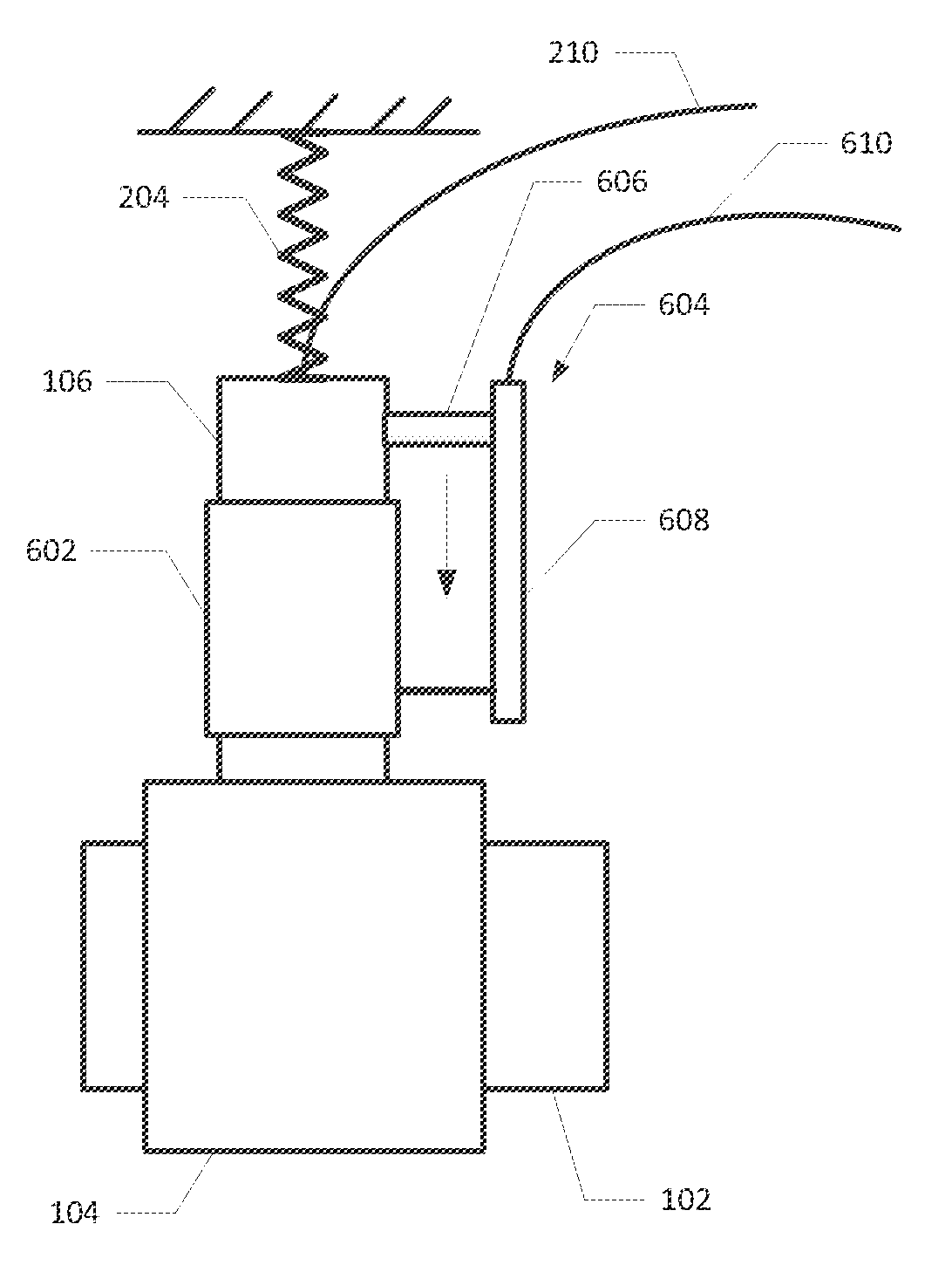
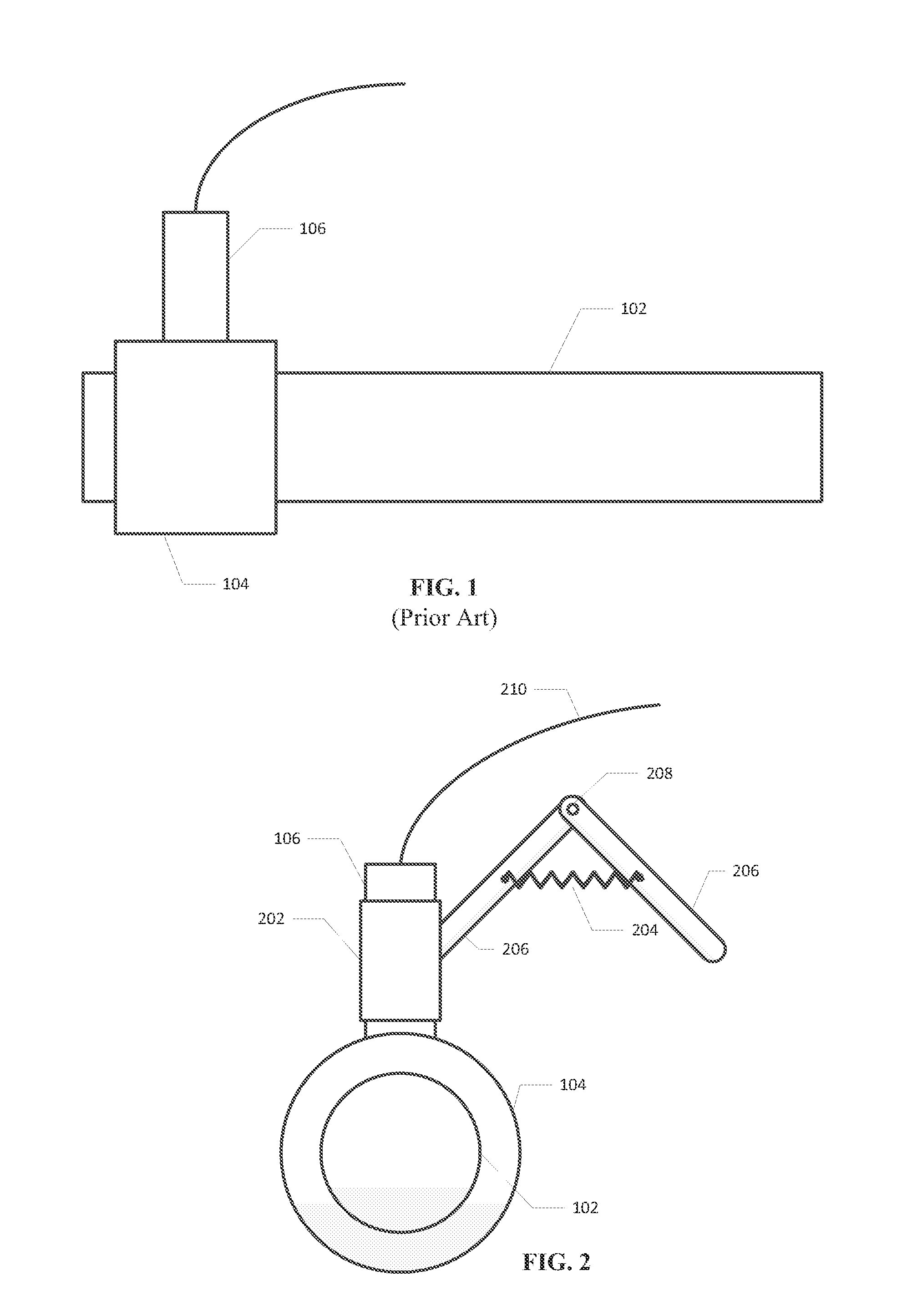
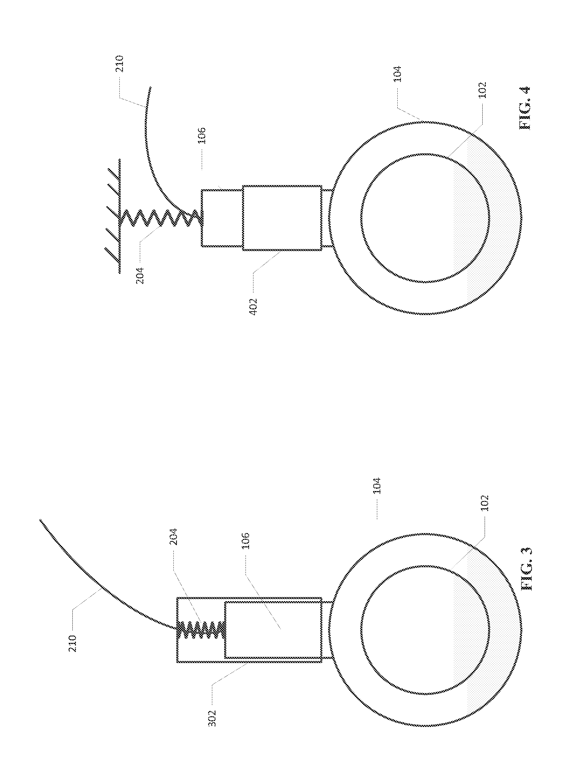
BACKGROUND OF THE INVENTION[0001]Generally, electrical rotating machinery such as generators and motors use slip rings and brushes to transfer current to and receive current from rotor windings mounted on a rotor. For example, FIG. 1 illustrates an embodiment of a rotor 102 having a slip ring 104 mounted on or attached to the rotor 102. An electrical brush 106 is in contact with the slip ring 104. Electrical current passes through the electrical brush 106 into the slip ring 104 or from the slip ring 104 into the electrical brush 106. The electrical brush 106 is typically held in position by a brush holder (not shown). Also, typically one or more springs (not shown) are used to apply pressure to the electrical brush so that contact between the brush 106 and the slip ring 104 is continuous as the slip ring 104 is rotated by the rotor. Typically, the electrical brush 106 is at least partially comprised of conductive carbon graphite. This material tends to wear over time as the slip rin...

Claims


Application Information

Patent Timeline
Patent Type & Authority Applications(United States)
IPC IPC(8): G06F15/00G01B21/04G01L19/00G01B21/02
CPCH01R39/58Y02E10/725G01R31/343H01R43/14Y02E10/72
Inventor SCHIEKE, SASCHAKOPPIKAR, ADITI YOGINSPORER, MARK ANDREWLEE, CHONGCHAN
Owner GENERAL ELECTRIC CO
Learn More